Wednesday, 17 August 2016

2 More DL4s

Big Green Delays, again.

I had a couple of these Line 6 DL4s handed over for repairs and each had a different problem from what I have seen before, so I'm holding out that this will be interesting to someone.

Silver-Taped Green Delay


By now I have something of a checklist of problems for these pedals. This one had all power supplies present, and none had any strange ripple or noise superimposed. Next step is to look at the test pads - there was no clock signal anywhere. Since the MCU generates the clock, and the MCU is responsible for resetting and waking the DSP (which produces the sampling clocks) nothing will work without this master clock.


U7. Oscillator and caps swapped at this point.

I know the problem is likely to be in the area of the MCU (U7). I replaced the oscillator crystal and capacitors with parts from the scrap board to see if I got a clock signal, as that's an easy place to start. No luck. I took off the MCU with hot air and replaced it with the one from the scrapper and everything worked again. Fantastic.

After removal and wicking of U7.

Alignment of the replacement is not great, but solder joints look good and function perfectly.

These MCU are a cheap 8051 core in a "ROMless" configuration, meaning that they have no ability to be programmed and only load code from external memory. This is a Good Thing for repairs, as it means that a scrap unit isn't really necessary, any new IC of this model should work, and all the code is in the one socketed EEPROM. In practice, I have found that "ROMless" is sometimes a misnomer. MCUs often have fuses or configuration bits that need to be programmed, or even have a small area of programmable memory for a bootloader, so a straight swap isn't always possible. More on this to come.

Normally I use a Kester flux pen for surface mount work, but this was the first time I used a syringe of tacky flux paste. It is really amazing stuff and I am completely won over. It made this job much faster and cleaner (I used it again for the Whammy repair, but unfortunately I'm getting to write about these out-of-order).


The owner had cover this pedal in silver gaffer tape. I think it looks cool.

A New Power Issue

This unit didn't get as far along before something look wrong. It had a working 3.3V supply, but all other power supplies voltages were low.

Another Rev 6 board.

The 6.6V voltage doubler (MAX660, U20) follows the 3.3V supply, so I started there and removed the output cap (C48) and IC. Measuring resistance across the output cap pads (6.6V to ground) gave 29 ohms, so there is still a problem.

U20 & C48 pulled.


The 5V regulator is next (U21, LM3480) so that was pulled, and the 29 ohm to ground was gone. I pulled U21 from the scrap board and replaced it, then repopulated U20 and C48. All power supplies returned and relays clicked, worked again.

Poor focus, but U21 has been replaced.

LEDs and relays are working after C48 and U20 are back.

At this point the scrap board I have is looking pretty bare. Between the 3 pedals I have written about and another personal unit that hasn't been fixed yet I've removed pretty much every IC. This is fine though, as I found out that very little (if anything) on these pedals is pre-programmed. In nearly every case new parts will work perfectly, having a donor just means avoiding waiting a day for replacements to be delivered. This shouldn't really be surprising as these are consumer goods made in large quantities, it makes sense to keep any custom, selected or programmed parts to a minimum to keep costs down.

Saturday, 6 August 2016

Digitech Whammy 4

I have a bit of a backlog of stuff I've done but not found the time to describe here. It's probably best to do so before I forget everything.

Big red pitch shifter. Another 90s digital classic. I used to own one of these these but moved it along because I didn't really get on well with no polyphony and the artifacting didn't always sound too great. I think these older Whammy pedals are pieces that need to have music written with them in mind instead of just switching them on and playing the usual stuff.


A pedal large enough that the photos look terrible

Sold as not working and had had a true bypass mod done. I was hoping that it just needed calibration or that there was a simple issue with the true bypass work. Instead it just flashed all the LEDs once when powered up and then did nothing.

Inside we have a large PCB that fills most of the enclosure. There's another Motorola 56k DSP56362 (same as some of the Line 6 and EX stuff), an Atmel 89C55 (8051 architecture), a Cirrus CS4224 Codec, the MIDI optoisolator and some CMOS logic chips and opamps. The DSP56k/8051/CS4224 seems to be a really common choice of components for late 90s/2000s digital, it's very similar to what was in the Line 6 pedals I looked at previously.

The mod work was pretty bad, the wiring used was way too thick and was under strain, there were ferrite beads cracked off the PCB and the 3PDT footswitch fell apart when I was removing the old wiring.

Main PCB and LED/encoder PCB

Atmel 8051 MCU under the sticker

This has the annoying 80s/90s practice of including an AC power supply to create positive and negative voltage supplies instead of using switching converters and running off 9V DC. There are 3 linear supplies, +5V and -5V for the analog stuff and 3.3V for digital. The 3.3V was down near 0V and the regulator looked scorched, so the heatsink was desoldered and I replaced it. No change, so there is excessive current being pulled somewhere. 3.3v to GND measured around 40 ohms. I removed any 3.3V bypass capacitors in case they were shorted, and then noticed that the main DSP chip was running pretty hot.

At this point I gave up for a little while. The DSP is a 144 pin QFP and in it can be difficult to find reliable suppliers of these 56k series parts these days. There are also no schematics for this pedal online, so I would have to trace things out or make guesses.

I tried contacting Digitech and asking about a schematic, and they replied with a PDF within an hour! Here it is https://drive.google.com/file/d/0ByVCt2OFhXnyZS1JZFlmb0Z3VTA/view?usp=sharing&resourcekey=0-vBilBFlfU0YChMUrFsavrg

I also found that this IC is actually still stocked at a lot of distributors, just not in huge numbers. I decided to get one from Farnell for around 18 euros, Digikey have them as well.

Removed the original bad DSP was difficult, as the chip is quite big and there is a large top-side ground place surrounding it that takes a lot of energy to heat up. After not much progress with hot air I flooded all the pins with some Chip-Quik low-temperature solder that I had. This kept everything melted and worked well but made a mess, there were blobs of solder all over that region of the board that had be wicked and scraped off. I realised afterwards that I should have tried using a larger air nozzle for a chip this big.

After DSP removal, there is solder everywhere
After wicking and cleaning the board

 The new chip went on easily enough with some tacky flux. The true bypass mod removes the original momentary footswitch, but this switch is still needed to calibrate the footpedal, so it is usually replaced with a pushbutton mounted to the back of the enclosure. In this case, the switch was connected to the board using the original connector and then fixed down with a big blob of hot glue (you can see this in one of the pictures above). Unfortunately, all the rework heated the board enough that this glue melted and ran all over the board, leaving a thin layer around the MCU. Now nothing happened when powering it. I could peel off  some of the larger pieces of glue but most of it needed to be scraped. At this point I gave up temporarily again.

DSP resoldered,Glue cleaned, C52 replaced, Y1 removed, cleaned and repopulated
I came back a couple of weeks later and used some IPA and cotton swabs to get off the rest of the hot glue. C52, Y1 (crystal oscillator), the momentary switch connector and some of the legs of the MCU were the worst effected, so I removed all of those except the MCU and cleaned the board as best as I could. Y1 was pretty badly coated in glue, so I cleaned it and repopulated. I tried poking around wit an oscilloscope probe and found that every time I touched one of the pads of C52 the LEDs would flash. The schematic says that this is the reset timing cap, so presumably the MCU was never being reset. I replaced it with a 1uF film cap I had on hand and the Whammy fired up. I can only guess that swapping the DSP was successful, but that the hot glue was preventing Y1 from oscillating and the MCU from getting a clock signal, or C52 was bad, or both. After redoing the true bypass wiring everything works.

There is also a 1k serial EEPROM on board, but it is connected to the DSP and not the MCU, so I think it for saving calibration settings and not the program code. I would like to dump the MCU if possible, but I'm going to leave this alone. If I come across a scrap board I'll pull the chip and try to dump it. There is also a JTAG debug port wired to the DSP, I haven't looked at that at all.

Was this worth it? Replacement parts ate up a good portion of what I would have gained from selling this, and I have more than a few hours invested in it, so probably not. The newer models add polyphony and have lowered the value on these older units too. I'll add a LED (mysteriously missing? Maybe someone killed this halfway through a mod) and sell it on. I'm glad to have swapped out a QFP144 successfully and found a schematic for this, so I'm still thinking of it as a win.

Tuesday, 19 July 2016

Electro-Harmonix Nano Pog

Polyphonic pitchshifter, in a small box, put into a bigger box. I forgot I did this one. I took a look at this around November 2015 for Moose Electronics who was doing a custom re-house with mods for someone. The pedal had stopped working somewhere between coming out of the original enclosure and going into the larger one he had made for it. I found some pictures on my camera and I actually took some notes, so the details shouldn't be completely hazy.

Work in progress pedal. Wiring was temporary.

ADSP-BF592
Surprisingly, EHX seem to have several different digital designs on the go, using pretty different architectures. They even have multiple polyphonic pitchshifters on the market, with the POG series competing with their Pitchfork. I guess they may be doing some market segmentation and charging more for the established Pog brand. I have also heard that they may be using different designers for different products, which might explain why they use different processors in some products instead of a single unified architecture.

The insides are typical modern EHX, board-mounted jacks, power connector and pots, with a soft-touch momentary switch for bypass. Bypassing is done with a DG419 analog switch, which is a little unusual as they normally use a 3DPT mechanical true bypass (possibly why this was rehoused?) For anyone wanting to convert these, you can short the switch pads and the pedal will always start up in effected mode and stay there. There is a huge programming/debug connector in the top-right.

The Nano Pog has an Analog Devices Blackfin DSP (ADSP-BF592 http://www.analog.com/en/products/processors-dsp/blackfin/adsp-bf592.html#product-overview) doing nearly all of the work. This is a more modern and significantly more powerful part than I usually see, most digital pedals I've looked at recently have used the older Motorala/NXP DSP56k series. The part will run at 200 MHz but I didn't think to look at any clocks on the board (I also didn't have an oscilloscope with any hope of seeing 200MHz signals at the time). AKM AK4552 24bit/96kHz codec is handling conversions.

A TI TPS61620 (http://www.ti.com/product/TPS62120) forms a step-down regulator to get a 3.3V supply from the 9V input. TPS60403 (http://www.ti.com/product/TPS60403) is using as in inverting charge pump in a neat SOT23-5 package. Apart from some opamps (TLC2272C) and an EEPROM that's pretty much it.

This thing had a pretty awful sounding distortion that farted out badly on low notes. The effect could be heard and it tracked correctly, so the digital guts were working correctly. I usually check all for power voltages first, wherever is immediately convenient. The DSP was getting 3.3V. I know what to expect with the opamps, looking there found 9V at V+ and something like 0.5V at V-. Poking about the board found that the charge pump had the same mystery voltage on it's output. The ceramic output cap (C39) is right at the edge of the board and looked like it had been cracked, maybe from taking it out of a tight-fitting enclosure. Not the best layout decision but it probably doesn't matter as most people won't be taking these apart. The datasheet (http://www.ti.com/lit/gpn/tps60403) recommends a 1uF output capacitor, and I had a sample kit of 0805 ceramics, so I tried replacing it. I now had -3.3V at the opamp negative supply pins. I don't usually see +9V and -3.3V supplies like this in pedals. Opamps will work fine with asymmetrical supplies, their outputs will just be limited by them in the usual ways. Pitchshifting should have unity gain, so there's no need for huge output drive. Low voltage charge pumps are easier to find these days too, most won't handle a 9V input. I just don't know why this was chosen over the usual virtual ground/split supply system, as that would allow similar headroom and would eliminate an IC.

Anyway, this was a quick enough fix and it sounded clean afterwards. The polyphonic tracking is cool and it doesn't have much of the shrill digital artifacts you can hear on the octave-up settings on some pitchshifters. I only played with this briefly before handing it back, and although I liked it it didn't exactly inspire many applications. I might need more time with these.


Finished rehouse.

The final version came out great, I think additional A/B outputs and some momentary switching were the custom options.  https://www.facebook.com/mooseelectronicsdublin/

Sunday, 26 June 2016

Electro-Harmonix Soul Food

I don't think I need to talk too much about this one, there's a lot of info online already (not enough pictures though. Photograph your stuff). This is EHX's budget version of the Klon Centaur, apparently with very few changes from the original.


This one arrived dead, nothing happens when power is applied. Probing around with a 9V supply connected doesn't find voltage anywhere. I started at the DC jack, and found that there was no continuity between the tip and the PCB. After desoldering, the DC jack still had an open circuit internally. This was probably mechanically damaged.
The 3PDT footswitch board has the True Bypass/Buffered Bypass switch of the original Klon and KTR.

D2 & D3 do not look like the "magic" Klon diodes. Internet consensus says they are Schottkys.
With a new jack installed it still had no power to the ICs. Diode D4 is connected across 9V to ground as reverse polarity protection, but as there is no series resistor D4 had become shorted, presumably by an incorrect power supply. I pulled it and replaced with 1n4007 as I have a lot of those. Works as expected now.

I would imagine there were two incidents that caused it to end up like this. Someone used a power supply of the wrong polarity and burned out D4, and someone broke the jack by forcing in the wrong connector or stepping on the power cable while it was plugged in.

For anyone else working on these modern EHX pedals, I have found that plastic spudger tools that are sold for opening electronics (particularly phones) work quite well for pushing on the DC jacks to remove the PCB from the enclosure, and don't leave any scratches.

Tuesday, 24 May 2016

MXR Smart Gate

Another eBay purchase. MXR have done a few noise gate pedals but this is one is fairly recent (2008? 2009?) so I'm expecting something reasonably complicated, similar to the ISP Decimators. As I got it nothing happens in effected or bypass mode, just dead.


The small MXR enclosure is quite packed on the inside, four quad opamps and a lot of passives that look like 0805 packages. Interestingly these are TL054, precision versions of the commonly seen TL074 & TL084, so that suggests some actual DC instrumentation is going on instead of just amplifying and clipping guitar signals. I think the construction style is pretty standard for modern MXR/Dunlop/Way Huge stuff, red PCBs, surface mount, PCB mounted hardware.


There are actually two boards, the second has all the hardware (PCB-mounted) and a Coolaudio V2164M, a quad VCA which is sold as an equivalent (clone of) the SSM2164, which must be doing all the downwards expansion of the gate.

Looking this thing over I found that only one opamp was getting power when I plugged it in. All the VCC pins of the other ICs had continuity with each other, but not with the 9V supply or the one powered chip. I would normally be tempted to just run a jumper wire to 9V and see if that fixes things, but I wanted to see where the power supply connection was lost.
From the reverse polarity diode and main bypass capacitor in the lower right hand corner, the 9V trace runs to one IC and then underneath the input jack. I couldn't follow it anywhere else, so I decided to desolder the jack.

Open via underneath input jack.

Here's the problem, the underside of the jack and the PCB were quite corroded. I would guess that some liquid may have gotten trapped in there after reflow soldering the board and before the large through-hole jacks were soldered. I had already cleaned away all the green crap in the above picture, but one via is visibly corroded and green and does not connect to the other side of the board. This one was carrying 9V to the rest of the pedal.

Corrosion on the input jack


I could have scraped away at that via and tried to solder it through, but I didn't trust that, especially underneath a jack. In the end I ran a wire replacing the track, there was a convenient tooling hole in the PCB I could run it through to connect on the other side. The gate works like new again.

As to what's learned, I guess that's not a very reliable track to run power on. Looking at the board it seems like the trace could be considerably wider, which would not have corroded as quickly. What is surprising is that none of the vias on this PCB are tented, which is usually a very cheap/free option with most manufacturers. If that power via had been covered in soldermask the pedal would likely have never failed.

Monday, 25 April 2016

Line 6 MM4 Repair and DL4 Conversion


I think these are fairly well known. The big 4-switch pedals have been very successful, especially the Big Green Delay (DL-4) which was something of a game-changer in popularizing live looping. The basic idea of the series was large, robust floor units that grouped Line 6's modelling technology into different categories bases on effects type. This is the "Modulation Modeler" and does chorus, phaser, flanger, tremolo etc. The FM-4 did filter effects, and apparently there were Amp Modeler (AM-4) and Distortion Modeler (DM-4) units that didn't sell well. I guess the people buying these pedals didn't want Line 6 POD-style sounds, and everyone else saved some money and just bought PODs.

This is a beat-up unit I got from eBay, sold as not working and missing the footswitches and knobs. It doesn't seem like a lot of people are buying these as projects, despite used units holding their value very well for a late 90s digital effects (the DL-4 especially). You can see why: digital, surface mount, fairly complex.

Backside of the board just has a socketed EPROM

Main board


There is quite a lot of info on this series online. This thread at freestompboxes.org has a complete service manual that includes full schematics and BOM for most revisions http://www.freestompboxes.org/viewtopic.php?t=23282&p=256501 for anyone who wants to play along.

All the pedals in this series are built on the same PCBs and have the same housings. The differences come down to which parts are populated (the DM-4 and AM-4 are mono only) and which firmware is in the EPROM chip. There's an NXP DSPB56364 DSP doing the audio processing, an 80C32 microcontroller for reading inputs/housekeeping and a Cirrus CS4223 24-bit 48kHz audio ADC/DAC. The rest of the board is some CMOS logic gates for sequencing LEDs and relay switching and some reasonably complicated voltage regulators for power. Nearly all parts are available as replacements, except for the DSP which is discontinued but still for sale from surplus and grey-market sellers.

This board seemed to have power issues, as I couldn't find any voltage rails that seemed correct. The Line 6 power supply is 9VAC and the internal DC supplies are pretty convoluted. 9VAC is fed through a 3.6 V zener and 1N4002 diode and connected to a MAX887 buck regulator (U14) producing 3.3V. The 3.3V supply powers some of the digital side, and also supplies a MAX660 voltage doubler (U20, giving 6.6V output), which is further regulated by an LM3480 5V regulator (U21). Finally, a LM2664 charge pump inverter (U15) produces -5V. The + and -5V rails are used for opamps throughout and 3.3V and 5V power the digital ICs. There's a very good post at the diystompboxes forum covering troubleshooting of these supplies http://www.diystompboxes.com/smfforum/index.php?topic=41142.msg297051#msg297051

" ..so the most likely suspects are
1: 3,6v Zener ( D16 )
2: MAX887 ( U14 )
3: MAX660 ( U20 )
4: LM3480 ( U21 )"

It's worth noting that the MAX887 has a shutdown pin that is switched by the input jack. The voltage regulators won't start up unless you have a cable in the input jack.

I had no 3.3V supply so I suspected the MAX887 and the diodes at the input. I replaced D11, D12 & D16 and applied power. The MAX887 immediately blew a hole in it's case and started smoking.


I removed the MAX887 and R49. R49 measured good out of circuit so I put it back. I tried powering up without the MAX887 and C40 (1000 uF) exploded. After removing it I had a close look at the board. There were some jumpers from battery contacts to the DC jack that look like a previous repair attempt. There was another jumper on the topside from the DC jack that I removed.

WTF
After buzzing out the connections from DC jack to the voltage regulators I found a burnt track from the input choke (which is not populated) and D16. Maybe this was an attempt to fix that? I have no idea. I am lucky to have a spare DL-4 parts board courtesy of Moose Electronics Dublin (check him out https://www.facebook.com/mooseelectronicsdublin/?ref=br_rs). I swapped over the MAX887 from the spares board and jumpered over the damaged track. Now the 887 regulator circuit buzzed audibly. OK, it probably can't start up as C40 is missing. I swapped over C40 from the scrap board and now I had a correct set of voltages at each regulator. I pushed one of the switches and the relays clicked and LEDs lit up, working again. I have to use a screwdriver to push the switches until I can get some replacements but everything functions correctly.

There are 4 testpoints on the main PCB that can be used to validate if things are working. When viewed on a scope, MCLK should show a 12 MHz clock signal, SCLK a 3 MHz clock, LRCLK a 47.8 kHz clock and ADC and DAC should show data changing at around 1 MHz. DAC will only show data if you have a cable in the output jack.


DL-4 Conversion

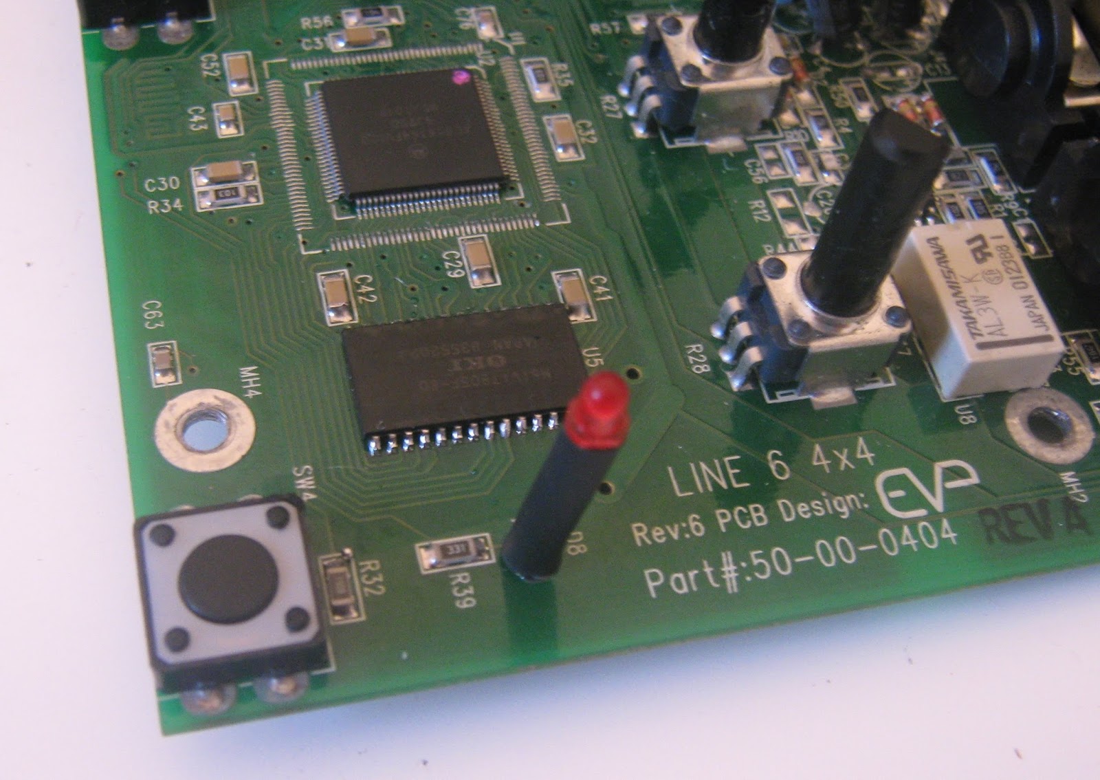
Ok, so the difference between pedals in this series is just what software is loaded, so can we convert one to another by swapping ROM chips? I tried the EPROM from the scrap DL-4 board (marked DL-4 V1.3) in the MM4 and it doesn't work, the pedal is non-responsive. Comparing the two boards it looks like the only difference is that U5 is not populated in the MM4. This makes sense, U5 is a 16mbit DRAM. The DSP has a small amount of RAM that can hold enough audio for effects like flangers, but the DL-4 has long delays and a 14 second looper so some extra memory is needed. I attempted to transplant U5 from my scrap DL-4 to the working MM-4.

U5 on scrap board. Pots and some caps had already been scavenged.

U5 desoldered.


U5 came off with hot air after a few minutes. Unfortunately the two boards are of slightly different revisions and the footprints for U5 are different, so this was a tight fit on the MM4.

MM4 prepped for populating U5.
U5 soldered.
After soldering I tried the pedal with the original MM4 ROM chip (the socketed PLCC32 on the backside of the board) and it still worked as an MM4 with the extra memory added. I swapped in the DL-4 chip from the scrap board, and now it works as a DL-4 as well. I thought I might have gotten the pedal to lock-up in DL-4 use but this was probably because I didn't know how to use a DL-4 looper, it seems to work correctly after playing around for a half hour.

So it seems you can convert these pedals as long as the memory needed for the delay is present. I dumped the contents of both chips to PC. I also have a dump of an FM-4 I got online, but all of the PLCC chips in these pedals are one-time-programmable and can't be overwritten. I'll have to order some EEPROMS to try the FM-4 firmware. If anyone has dumps of the AM-4 or DM-4 please get in touch, it would be fun to try these, even if just for completeness.

I think it should be possibly to modify any of these pedals to switch out firmware and reset the DSP to go between DL-4/FM-4/MM-4/whatever at will, possibly on a footswitch.

Sunday, 24 April 2016

Effectrode Delta-Trem

Something fancier than I normally get to play with. This is a stereo tube tremolo by "Audiophile Pedals" company Effectrode http://www.effectrode.com/delta-trem/delta-trem-in-depth/
2 12AX7s doing volume modulation, with controls for speed and depth of modulation as well as a "shape" control that blends between different LFO waveforms. This is an older 3 knob version, the current production model adds a "rhythm" control and changes the tubes to 12AU7.

I'm taking a look at this for a friend, apparently it was used with the wrong power supply and is now dead.


After opening it up, I'm surprised to see it's a mixed analog/digital design. There is a 8 pin SOIC PIC 12F5091 microcontroller acting as a switch-mode power supply controller and a second larger PIC 18F2620 reading the pots, switch, driving the LEDs and bypass relay and generating the LFO. Nice sealed Omeg pots for all controls. Switching FET is IRF740AS. There is also an IRF FL210 FET, I'm not sure what that one is doing as I didn't trace it out. The SOT23 transistors appear to be FMMT717 and FMMT617.

After powering the pedal with the correct 12V DC the 78L05A 5V regulator was not working correctly (high output voltage). I tried replacing it with a 78L05 in a TO-92 package but eventually found that the 1206 R470 resistor in series with the power jack was burned and was reading high (Mohms), limiting current to the regulator. A 1206 resistor is usually rated for about 1/4 W so I replaced it with a 470 ohm through-hole 1/4 W resistor. Still doesn't work. Whoops, "R470" means 0.47 ohm, not 470 ohm. I swapped in a 1.2 ohm resistor (closest value at hand) and it fired up.

It sounds very good, and gives a great variety of authentic amp-tremolo sounds. It doesn't really go beyond this into more extreme territory or do industrial-style hard chopping. There might be a slight volume drop, but that could be something inherent to all tremolo effects. Personally I don't know if I like tremolo enough to need an accurate tube version, but I guess I'm not really the target audience here. I didn't take apart the optocouplers as this is not my pedal but I am fairly sure they are just neon bulbs and cadmium sulfide photocells heatshrinked together.

There were a few things I didn't like. A microcontroller as a SMPS controller doesn't sit well with me. This increases development time and is another part that needs to be programmed before assembly, all for a controller that will have slower loop response than a dedicated controller IC, which could also cost less. It's also annoying from a repair point of view, if the microcontrollers are dead they can't be replaced without access to the firmware. I find this acceptable for the larger controller (but manufacturers, please provide people with binaries so they can fix their stuff!) but I can't see any reason why that 8 pin PIC needs to be programmable.

The SMPS provides the high voltage supply for the tubes, the 12AX7 cathodes are sitting at 251V. However there are no high-voltage warning on either side of the PCB, it's pretty easy to open the thing and touch a capacitor charged to a couple of hundred volts (ask me how I know this). The PCB is also unusually difficult to solder to and seems to suck heat away. I don't think there are any internal layers so I guess the copper might be extra thick? I can't see any reason why this would be needed. Finally, I feel that something in this class should be bulletproof in terms of surviving the wrong power supply. I'm not sure what was used when this thing died (probably an AC supply) but I have seen much cheaper pedals survive quite a bit of abuse without burning anything out.

I never had the correct power supply, but it needs a little over 600mA at 12V, maybe more if the tubes are starting off cold.