Sunday 19 November 2017

Eurotec Black Box Faze Module

Eurotec was a brand run by Sola/Colorsound in the late 70s. They released a line of pedals called the "Black Box" series which seemed to be re-issues of their earlier products as well as some clones of contemporary designs. The pedals could be used individually with battery power, or plugged into a "Black Box Module Energiser" base station that could power and route signals to four modules. I don't know if this modular system was successful but it's interesting to see an earlier commercial stab at a pedalboard concept.

Image from https://www.tonehome.de/eurotec/


I have the phaser of the series, and it doesn't pass an effected signal. There are no schematics for this series that I could find online, but 4 JFETs and 4 opamps nearby give the game away - this is most likely a Phase 90 clone. The "React" knob seems to replace the mixing resistors for the clean and wet signals on the original so the phasing effect can be adjusted in intensity.

Build quality is a little cheap, but not unusual for the period - a single sided board that looks like a phenolic substrate. Traces will probably lift if overheated. The footswitch is unlike any I've seen before, it has a threaded black plastic cover to anchor itself to the enclosure. The enclosure is more like a sheet metal can than the usual diecast aluminium.


I went through this expecting to find some dead capacitors, but everything measured OK out of circuit. I did find one capacitor lead that had either broken loose from a cold solder joint or was never soldered in at the factory.


Feeding a sine wave into the pedal and probing the opamps showed that all had phase-shifted signals on the outputs except one - replacing this opamp restored the effected signal.


It really sounds great - the "react" control will dial the phasing all the way to a very resonant "thumping" sound - it can get much more extreme than the MXR originals.

Adding external power:

Despite having an LED, there is no indication that the pedal is active when pushing the footswitch.

I found it interesting that the output jack on these boards are stereo, and the ring contact is tied to a diode that switches out the battery clip. Pictures of the original base station seem to show stereo TRS jacks, so it's possible that they supplied power through the additional conductor.

Full modular system - image from https://www.tonehome.de/eurotec/

I wired up a a mono 1/8" jack to a stereo 1/8" connector and added a 9V DC connector to the ring. When plugged into the output jack, the output signal is passed through and 9V power is used instead of the battery. As a bonus, the LED works as well.


This seems like a worthwhile cable if you don't want to modify the enclosure.

Tuesday 14 November 2017

Digitech PDS 1000 & 2000 Repairs

I am fond of the Dod/Digitech PDS series delays. On paper there's nothing too amazing - mid 1980s 8-bit delays with 1, 2 or 8 (if you can afford the PDS 8000) second maximum delay times. There are two features that win me over.

The first is the "Infinite Repeat" footswitch that locks the delay into a repeating loop. The loop can be pitch-shifted by changing the delay time, and when Infinite Repeats is turned off the delayed signal trails out like normal again. This is like playing with the shittiest looper and is a lot of fun, and surprisingly a lot of modern delays & loopers don't (or can't) do this. Some will repeat indefinitely without oscillating if the feedback is maxed (Boss DD series) but it's nice to have it on a dedicated switch, with feedback control available and ready for switching back to "normal" use. A surprising amount of 90s and early 00s delays can't smoothly pitch-shift recorded audio when playing with the delay times, and glitch or "jump" somewhere through the pot travel.

The second win is the internal design. The expected parts for a simple delay are all there - an ADC, a DAC, some memory and some logic gluing things together - but there are no custom ASICs, microcontrollers or programmable devices at all. Everything is done with standard CMOS logic. These delays could be built from scratch with new parts today, and they are very repairable. This is a little bit of a backwards approach for a 1985 era product - at this point Boss had already released the DD2 & DD3a delay pedals and they used the same ASIC from the Roland rackmount digital delays. This could have been a cultural difference, as Japanese manufacturers seemed to prefer going for custom ICs and offsetting the cost against using them in lots of products (Yamaha have also done this). Digitech (or DOD at the time) may have to bring the series to market quickly, which could have forced them to use off-the-shelf parts. Whatever the reason, nearly ever part can be sourced pretty easily, unlike finding a replacement Boss controller IC from 1985 (good luck).

I repaired 4 of these delays recently. Here is a braindump:


PDS 2000 #1


All of the pedals in this series came with snap-in plastic battery doors that are not held captive by the enclosure (i.e. they are removable). This means they get lost, and I have never actually seen one.

This PDS 2000 (mine) was fairly easy to deal with. It's a 2 second delay that adds sampling modes that can trigger the delay sample by a footswitch or an external trigger signal. It had some broken wires in the harness between the PCB and jacks/switches. I think this is due to using the pedal with a battery but without a battery door - the weight of the battery pulls on the wiring if it's free to swing around on the end of the battery clip. This just needed some soldering to bring it back.

The footswitches were also unreliable, so I replaced the microswitches. More on that below.


In an unusual move, DOD actually sprang for a silkscreen print on this PCB. Schematics are available online but can be hard to match them with a PCB when there is no silkscreen and no part designators.

PDS 1000 #1


This one was partially working when I got it. The output jack wouldn't hold a cable in, the footswitches rarely worked and the delay length maxed out about 75% of the way through the pot's travel - but it did work as a delay. I replaced the footswitches and bent the retaining lug on the output jack (I may go back and replace this) so that it was a usable effect.


I have never seen a PDS 1000 schematic, but the PDS 1002 2 second version looks like it's very similar. The delay time control circuit is shared across the earlier series. Delay time is varied by changing the frequency of the main clock signal that shifts digital samples into and out of DRAM memory. Faster clock frequencies shift data faster and give shorter delays. Delay time is adjusted by 3(!) potentiometers, the delay time pot on the front of the enclosure, a trimpot that adjusts range of the of the main delay time pot, and a final trimpot that globally adjusts clock frequency by small amounts. You don't really get a very wide range of adjustment so trying to get longer delays by tweaking pots might not work too well.

Tweaking these delay pots brought the delay back to 1 second and adjustable through the full range of the delay pot.

PDS 2000 #2


This is the only pedal of the 4 that didn 't power up at all. None of the logic chips had any sensible voltage at the VCC pins, but the opamps were getting 9V. There is a 78L05 to drop the 9-10V input down to power all the logic chips, and this has a JFET soft-start circuit that ramps up the 5V power supply, presumably to protect the digital chips from a loose or intermittent power cable. I replaced the timing cap with no luck, then swapped the FET for a new J201 and it powered up.


This a soft-start for the 9V supply on the PDS1002. The 2000 has something similar.


Everything seemed to work, except that I couldn't change delay ranges, it was stuck on the longest range (2 seconds). The sampling modes also weren't quite right, trying to trigger samples would switch the pedal into bypass mode or sometimes do nothing at all. I traced signals back from the delay range switch to a 74HC04 hex inverter, which looked dead. I swapped this chip over from the other 2000 and it worked. I ordered a new 74HC04 and got two working pedals.

This one also was not quite a 2 second delay so I did some pot tweaking. Unfortunately I managed to slip with an oscilloscope probe and shorted two pins on the DRAM chip, and killed an input pin. I replaced with a TMS4256 DRAM from eBay - works fine. With the new chip the delay rates could be carefully dialled in to 2 seconds pretty quickly.

PDS 1000 #2


This was in the worst condition. I got this in a box of failed repairs from a music store in the US some years ago and never did a lot with it until now. Someone had already taken a crack at fixing it, it was missing knobs and a back panel. Two of the pots were broken, the bodies would wobble freely against the legs as if they had detached internally. The 1Meg trimmer for clock frequency was also broken off.


I replaced the trimmer and set it to the middle of the it's range, based on how the other 1000 was set. The PCB mount pots were a little harder, DOD use Alpha pots marked "W" which I don't think are actually W taper (W taper is logarithmic for half the travel, then reverse log for the other half). I replaced with long-leg alpha pots. The replacements are a little taller than the originals, so I cut the legs a little shorter and soldered some bus bar to them, then soldered the bus wire into the PCB. This actually worked pretty well, but replacing these pots and running wires to the PCB is probably a better long-term solution.


After replacing pots I found that delay time wasn't working because of broken trace, I ran some Kynar wire to restore it. The mix knob didn't work and it was stuck at 100% wet - this turned out to be another bad JFET.

At this point things appeared to work again, except the delay was very distorted and noisy. I messed around with compounder trimpot as I thought that may be distorting - no improvement. Eventually I realised that bad memory chips would give corrupted repeats which would probably sound like distortion, so I swapped the DRAM from the other PDS 1000 and it worked. I ordered some replacement DRAM (I used MK4564) and they worked just fine.

Adjusting delay time

There may be an "official" method for adjusting maximum delay length using a testpoint on the PCB but without a service manual I've come up with my own.

The capacity of DRAM can be looked up from the P/N and the nominal maximum delay in seconds is known. My reasoning is that DRAM should be completely filled in this time, so I probe the DRAM with an oscilloscope and adjust delay length until the frequency of data in and out matches the DRAM size divided by nominal delay length in seconds.

For the 2000 the DRAM is 262144 memory locations and max delay is 2 seconds, so I want data to be going in and out of memory at around 262144/2 times per second or 131072 Hz when the delay pot is all the way up. This can be measured from the DRAM Write Enable pin, and probably from the Data in and Data out pins as well. Most of the tweaking is done on the lower global clock frequency trim, usually after making sure the delay pot is working throughout it's whole range. Sometimes I had to iterate and go back and forth between the two sets of pots. Adjustment on trimpots is fairly coarse, so this can't be dialled with really great precision but I find it much easier than trying to listen to the delay and sync to a stopwatch or something similar.

Modding for more delay time

There are online discussions about modifying these pedals for longer delay times that usually involve tweaking the delay pots away from nominal positions to get longer delays. I think this will only work well for very lo-fi sounds, as the sample rate will get much lower and aliasing effects will get worse.

The delay loop in the PDS series is basically some 4040 ripple counters counting through memory addresses and resetting when the end of memory is reached. A better approach to extending delay time is replacing DRAM with a larger IC (or multiple ICs) and adjusting the counter reset logic to address the larger memory. I have some spare DRAM for both of these pedals so I would like to try this.

I haven't seen a schematic for the PDS 8000 (8 second delay). I would like to see how this was implemented, as it should have 4x the memory of the PDS 2000. Extending the 2000 to 8 seconds may be possible depending on how extensive the differences are.

The best picture I can find online shows a single 18 pin (not 16 pin) IC, but the label isn't legible. Presumably it's a 1Mbit x 1 DRAM.

Please let me know if you have a PDS 8000 schematic or high-resolution board shots.

There is a PDS 20/20 delay schematic available (http://www.experimentalistsanonymous.com/diy/Schematics/Delay%20Echo%20and%20Samplers/Digitech%20PDS2020.pdf) which uses 2 4464 DRAMs, which is twice the memory of the PDS 2000 but still only does a 2 second delay. America's Pedal has a catalog for the PDS series which explains why - the 20/20 has a delay signal bandwidth of 16 kHz, the rest of the series only has 7 kHz except for the PDS 1700. I am guessing the higher sample rate is for the chorus/flanger modes where really short delays are needed.
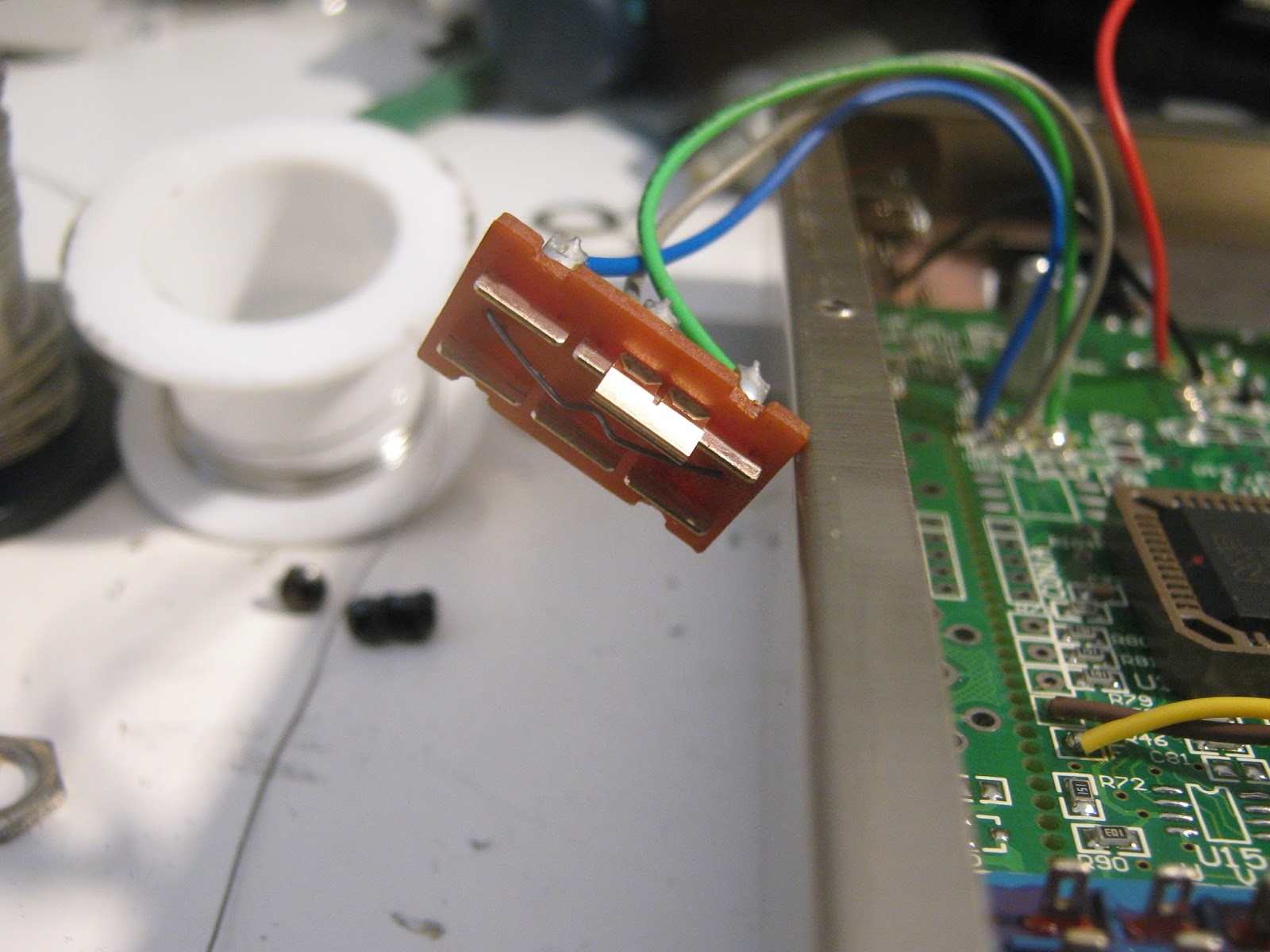
Footswitches

Dod used a fairly cheap mechanical design for actuating footswitch buttons on a small PCB. The plastic foot panels are cantilevered and are returned to their neutral position by a spring at the "fixed" end, not the free end which would make more sense. There is also no real end-stop to limit the force on the footswitch - if you stomp hard you will crush the button. This is problematic as most players will stomp harder if the switch doesn't work, so once they start to fail they deteriorate quickly.


There is advice online on adjusting spring tension to get a pedal to switch more reliably. Don't bother. If a DOD pedal does not switch every time, just replace the 10mm button on the PCB. They are very cheap and should last another decade of use. Play with the mounting hardware only if the levers aren't rotating correctly.

Tuesday 5 September 2017

Yamaha DDS-20M Delay/Sampler

I wouldn't really think of Yamaha as a guitar pedal company. They have made a lot of classical instruments, drum machines, e-drums and studio gear (I have an SPX90 I really need to repair) so I guess the pedigree is there. This is a mid-80s 2 second digital delay/sampler, from that period when putting "sampler" on products must have excited guitar players.

The mechanical design is a little different - all of the controls are recessed at a height below the footswitch and there is a "unibrow" along the top with the logos and LED.

There are no schematics and not a huge amount of info on these that I could find online, other than there was a range of pedals in this form factor. No signs of life.


After looking on the inside, I got the impression that someone else had attempted a fix. There was a resistor between the +9V and ground pads of the DC jack (?), the ground trace had been cut in two places for some reason and a wire had been soldered in to replace it. I can't see why the resistor between 9V and ground would be needed for anything other than wasting power, so I removed it. I also found that the ground from the DC jack was not connected to circuit ground. Adding a jumper was enough to get this to fire up with a DC supply, but not with a battery. It's possible that the resistor was originally connected between jack ground and circuit ground but as it was several kilo-ohms a wire would be a better solution.

The pedal uses a 2 board design, connected together with wires. Both are single-sided PCBs that look like a phenolic paper material and no through-hole plating anywhere. This is pretty typical for 80s Japanese electronics but it can mean that any board-mounted hardware can be fragile as there is only solder on one side of the board anchoring it place. In this delay, the output jack had taken some force (probably a cable was stepped on) and the pad to the jack tip had broken, this had to be re-soldered to get an output signal. One of the PCBs has most of the analog parts, the inner one has the digital controller and the pots and rotary switch.

2 wires added and a diode replaced

It still didn't work from a battery. Following the (broken) ground trace to the other side of the board I could see that a diode was used to switch out the battery when a power supply was used, replacing this diode fixed everything.

Analog board, component side

The analog board has a 4066 for bypass/effected switching, 5534 opamps, a Motorola M5218 audio pre-amp (I have only seen this part in Japanese pedals, I think the original Boss DS-1 used something like this), μpc1571 compander (NEC's NE571 clone) and the chip in the bottom left corner is an LM311 comparator. The comparator is forming part of a sigma-delta ADC with the digital controller, much like the Boss DD-2 and the Digitech PDS series of delays.

Bizarre vertical component assemblies

I thought the parts marked "< RIVER < RIVER" were SIP ICs, but they are actually components standing vertically! They seem to be clamped together at the top. I don't know if there was automated machines to produce these assemblies or if they were re-used in other designs but it's surprising that this was cheap enough to be worth the effort.


Digital board

The digital controller is an "M654131". No info on this, probably a Yamaha custom. Maybe they used it somewhere else in a different product. I don't have any pictures of the back side of this board so I don't know what type of memory is used. It looks like there are two 9-pin SIPs connected straight to the controller so I would guess 2 64k DRAMs, assuming this is an 8-bit delay.

It sounds great. I like that these early digital designs use companders and have simple master clock signals. It's like a holdover from the days of analog delay designs. This one can pitch-shift the delay signal smoothly, unlike some more modern delays.

Sunday 27 August 2017

Boss DD-2/DSD-2 repairs

Once again, I have a backlog of photos of things with very poor notes - hopefully I haven't forgotten everything.

Early Boss Delays

I've played a few of the early Boss delays, but oddly enough I've had none of the more common modern versions (DD-5/6/7 etc). The DD-2 is regarded as the first digital delay in a stompbox, using some of the tech from Roland's larger rackmount delays (see Boss's article on the history of delays). The architecture is similar to early Japanese delays, with one large custom controller IC doing all the digital work - a sigma delta ADC (with an external comparator), DRAM interfacing & parallel outputs for an resistor network DAC. This is the same RDD63H101 custom used in the famous Roland SDE-3000, often referred to as the "long chip" as it barely fits in the Boss stompbox case. Everything is synchronised off a single master clock which is directly controlled by the delay time knob - changing the delay time smoothly pitch-shifts whatever audio is memory without any glitching.

Digital section, from Boss Service Notes

Unlike many other 80s delay pedals, the audio is quantised to 12-bit samples (8 is more typical) for lower noise and there is also more memory than I would expected, 3 64k DRAM chips (a single 64k IC is common in some 1 second digital delays from the era).

Parts of the schematic look more like what would be expected from an analog delay, there is a NE570 compressing on the way into the digital delay line and expanding on the way out to further help with noise, and pre-emphasis and de-emphasis filters at 7 kHz to hide any sampling bandwidth limitations.

The custom chip is also a weak point in repairing these. If it's dead then the only way to find a replacement is to pull one from another pedal. I am hoping that most of these are still working and that faulty pedals just have power or memory issues.

DD-2 #1

This was another eBay purchase. It powered up, but only produced a whining noise. The noise would change in volume with the Level knob and change in pitch with Delay Time knob, so the digital end was the first suspect. Power from the 5V regulator looked good.

DD-2 #1

I had seen something like this before on an 80s Digitech PDS delay (write-up to come at some point in the future). In that case I was getting massively distorted repeats and I narrowed things down to bad memory, data was beings written in but garbage was being read out. I also knew that DRAM failure was very common in the late 70s/early 80s so I decided to try swapping out new memory chips on this DD-2.

All memory ICs desoldered
The 3 DRAM ICs are directly below the main controller. These pedals are absolutely crammed with through-hole parts, it's impressive that so much could be fit into the standard BOSS housing when you consider how much more simpler the earlier Boss pedals were in comparison.

Socketed memory ICs - a dead end.

Initially I tried to install sockets to make troubleshooting easier. After a struggle to get socket into the board I realised this wouldn't work, the flying leads over ICs would need to replaced with longer wires and it was possible the PCB wouldn't fit back inside the case.

Replacement memory installed.

I removed the sockets and installed 3 MK4164 64K DRAMs with a compatible pinouts. Switched the pedal on - absolutely nothing had changed. Shit.

Going over the each pin of the controller IC with an oscilloscope, I found that even though 5V was present, when I had a test signal connected to the input (a triangle wave in this case) I could see the triangle wave riding on top of the 5V supply! I traced this back to a cracked solder joint on the 5V regulator, which was then reflowed. The power filtering electrolytics were replaced at the same time. Another delay working again.

DD-2 #2


This much dirtier DD-2 was not mine, but was bought broken at a market for €5(!) and eventually found it's way to me to take a look.

DD-2 #2

This was a lot easier to figure out, the pedal wasn't lighting up and was shorting out my power supply. The reverse polarity protection zener diode (D6) was burnt out and failed as a short. It looked like someone had been in here before and had tried to jumper over a PCB track with a piece of wire and some cold-looking solder joints.

Previous attempt at a fix
 After removing the jumper and the diode (which tested as a short out-of-circuit) the board looked a little rough. I added a 1n4001 as a replacement and tried it out.

Some PCB foil damage
This time the LED would only come on when the pedal button was held down, it wouldn't latch and stay on. Usually Boss use a discrete flip-flop for switching (an excellent Geofex article on this) but in the DD-2 they use a BA634 flip-flop in a SIP package, probably just to save some real estate on the PCB. I thought this IC was bad but it just had a broken ground trace - another small jumper wire fixed it.

Both of these pedals sounded identical, and when I checked the calibration routines in the service manuals they were both still perfectly dialled, with max delay coming in at 800ms on both.

Bonus Repair: Boss DSD-2

This pedal is a couple of years newer. The problem was pretty obvious, all of the 1/4" jacks and the DC power jack were broken and had to be replaced. I can only guess someone was putting the pedals into a bag without unplugging the cables and they managed to break them all.

DSD-2

Guts - note broken jacks everywhere

What is interesting is how close the DSD-2 is to the DD-2. There are a couple of part changes for cost and space savings (the RAM chips have been replaced with SIP packages that are a better use of space) but it's basically the DD-2 without the hold mode and with an external trigger input instead as a "sampler" mode. The service notes even shows that the only differences in the digital side is that a couple of pins are wired differently on the controller to trigger a delay from the Trig In jack instead of the footswitch.

The DSD-2 should perform identically to the DD-2 in delay modes, and to my ears they sound identical. If you like this sound it may be worth finding a DSD-2/3 as they don't command the same prices as the DD-2.


Monday 14 August 2017

Electro-Harmonix Pog (Big Box)

binary is hereFollowing the Nano POG & POG2, here is the original big box Electro-Harmonix POG. The big POG has mostly the same set of features as the POG2 - it doesn't have presets and the filter has fewer settings, but there are separate detune sliders for the 1 & 2 octave up harmonies.

No slide pots were placed this time
In keeping with a trend I've noticed with EHX products, it's completely different on the inside than the other POG pedals. The POG2 and Nano POG use Analog Devices BlackFin DSPs, the OG POG is much more late 90s and has a DSP56364 and a 8051-style P87C52 MCU, just like some Line 6 products, or the Digitech Whammy. I have no idea why this cheap microcontroller family is so commonly found alongside the DSP56K series but I'm starting to suspect there is an application note somewhere that shows how to use these parts together. The AK4552 codec and 2272 & 5532 opamps are also very familiar by now. A TLV1543 ADC reads out the slider positions.


DSP56364

This pedal is also an outlier in that the complete factory schematic is online at Freestompboxes. The P87* series MCUs are OTP (but could be replaced with a compatible programmable part), so I have dumped this one. There is no other programmable part on the board so this should hold firmware for both the MCU and the DSP. The binary is here.
There are a lot of unpopulated parts in the PCB layout, some may be used for development and some look abandoned. There are footprints with silkscreen labels that indicate that they are for MIDI control and the schematic also indicates MIDI was planned at some point. I didn't experiment.

Trashed slide switch

No complicated fix for this one, once I had rigged up an 18V supply I found that the LPF mode switch was broken and a couple of wires looked like they were about to come off the board. After some solder touch ups everything worked fine. It sounds very much like the POG2, but as I don't own one anymore I couldn't do a direct comparison.

Saturday 15 July 2017

Ibanez FL9

A quick one. I got this original 80's 9-series flanger that didn't seem to be "flange-ing".

Ibanez Fl9

When plugged in it gave out that tell-tale "whirr" sound when power was applied that some kind of delay was happening. It sounded like the signal was delayed correctly and mixed in with the clean signal, but nothing was happening with the LFO, so there was no "movement". First thing to check is if the Speed pot is wired up or broken.


Back of speed pot

Hey, are those two lugs of the speed pot shorting together? I removed the pot and separated them with some needle nose pliers. The speed pot now varies the speed of the LFO and everything works as expected.

PCB topside

A quick shot of the board while I have this open. The BBD and clock generator ICs are MN3207 and MN3102, manufactured by Mitsubishi. Build quality is pretty high for what was standard at the time. All the electrolytic capacitors are Nichicon brands, some have "8138" datecodes so I think this is 1981 vintage.

The flanger sounds great, but is much more subtle than the MXR I looked at recently. This does chorus-style sounds much better rather than screaming airplane sounds. 9V operation is a bonus.

Line 6 Echo Park

The other Line 6 green delay. The ToneCore series was released around 2004, after the larger 4x4 stompbox modeller series. The series looks like they were intended to be small factor versions of models from the previous series, the Echo Park is something like a refined DL4, smaller and cheaper and shares a lot of the same delay models. It has the advantage of running off a standard 9V supply but omitted the looper that made the DL4 such a success.


Echo Park

In an unusual design choice, the pedals are split into two components, the "dock" (containing the main chassis, DSP, switches, jacks, power supplies and input/output buffers & amplifiers) and the "module" (holding the knobs, switches, a microcontroller and the program code for the DSP). This is the same idea as the DL4/FM4/MM4 series using the same PCBs with different program code, but allows different pedals to have different numbers or types of knobs and switches instead of shoe-horning everything into one shared format.

Modules and docks were sold separately and marketed as interchangeable. Red Panda even made a third-party module. Line6 released a programmable Developer's Kit module in 2008 that allowed hobbyists to create DSP effects that ran on the platform. This is a very cool idea but it doesn't look like it ever took off, there are very few examples online of anyone actually building anything.

This Echo Park was bought used and needing repair. The LED would flash once on when power was applied, but it was otherwise completely dead. I was hoping that I could easly isolate the problem to either the module or dock.

Unlike the DL4, there are no service manuals online. However, Line 6 did publish a ToneCore SDK Hardware Guide which has block diagrams and some slightly blurry schematics for the dock and the programmable Developer Kit module. The Developer module is not the same as the product modules, but it should be close enough to make repairs possible.

 ToneCore Dock


Dock, backside. Note test points.

Dock PCB, topside.

The insides of the dock look familiar, there is a DSP56364 dsp and some power and analog stuff. I managed to connect the dock and module together lying flying flat on my bench using some right-angle headers and some jumper wires so I could probe the signals between them. I was getting power and some of the clock signals were present, but I couldn't see any signs of the module programming the DSP when applying power (as the module contains the "effect", the DSP code must be stored there and transferred to the dock on startup).
There are testpoints on the backside of the PCB for MCU, DSP and ADC/DAC clocks, this is the place to look with an oscilloscope if you are debugging one of these.

Negative voltage generator

One interesting feature of this series is that they were the first (possibly only?) Line 6 pedal to run with a standard 9V DC supply instead of shipping with a bulky AC supply. The dock uses the 9V power and one of the clock signals from the DSP to form a curde charge pump to create a negative voltage rail of about -7V. This is pretty smart! I'm surprised it isn't more common in digital pedals.

Echo Park Module


Module PCB, as found

After opening the module it was pretty clear that someone had been in here before. Some traces were damaged and a SOT23 package device (Q1) was missing. A red jumper wire has been added. There are a lot of similarities with the schematic in the SDK manuals, the MCU is different (it's a P89LPC935F, an 80C51 derivative like in the 4x4 pedals) and the product modules add an SST25F512 SPI flash memory chip but otherwise it looks close enough to use as a reference for repair. The manual schematic shows that the missing SOT23 package is a PMBT4401, I didn't have one at hand but I did have some BC847C that should be a good alternative. The schematic also had enough information to replace the damaged traces with some jumper wires after beeping things out with a DMM.

After repair attempts. One of the switches was removed temporarily to help with following hidden traces.

So I added transistor and the jumpers, and... nothing. Just one short LED flash when it's powered up and nothing else. I suspected either the flash memory or the MCU in the module were bad, but the MCU was now expensive to replace and difficult to source, and I had no copy of the contents of the memory so there wasn't much that could be done. So this went back into the box and into the "fix" pile and stayed there for a year.

Second attempt:


The line-up


Eventually I got two more non-working Echo Parks to look at from Moose Electronics. Maybe I could mix and match modules and docks to figure out which were good, maybe I could even fix all three. I labelled these to keep track, mine is #1 and the new ones are #2 and #3.

Starting out, none of the pedals worked. The immediate good news from swapping parts was that my dock (#1) worked with the modules from #2 & #3. No other permutations gave me a working pedal, so I knew my module was bad and docks #2 & #3 were bad. I opened the bad docks and one of them had a battery cable pinched between some header pins and sockets. Nothing else looked obviously bad. When I tested it again it worked perfectly. Either moving that cable or reseating the header pin/socket connection must have restored power.
The other bad dock had no obvious damage, and looked like it had a dead DSP. None of the test signals on the backside of the PCB were present, and they should be generated by the DSP, which did have power. In this case it's actually cheaper to buy a less desirable ToneCore pedal just for the dock than attempting to swap out the DSP, so this Echo Park will be getting a replacement instead of a repair.

This just leaves my bad module, #1. Suspecting the serial flash or the MCU, I decided to desolder the serial flash and see if it could be read in my programmer, and what data was on there. The chip ID was correctly identified, but the contents were all 0xFF! Effectively this was blank and there was no program code for the pedal to run. I pulled one of the flash chips from one of the working modules and dumped it, and re-programmed the empty chip. After resoldering it, the pedal lit up and worked just like the other one. I can only assume that the soldering "accident" I saw either caused the memory to be erased or was an attempt to fix it, I can't be sure.

Desoldering U1

Dumping U1


So, if I had had a memory dump of this a year ago I could have fixed my pedal then. In the interest of helping someone out, here is the contents of the flash.