
I think these are fairly well known. The big 4-switch pedals have been very successful, especially the Big Green Delay (DL-4) which was something of a game-changer in popularizing live looping. The basic idea of the series was large, robust floor units that grouped Line 6's modelling technology into different categories bases on effects type. This is the "Modulation Modeler" and does chorus, phaser, flanger, tremolo etc. The FM-4 did filter effects, and apparently there were Amp Modeler (AM-4) and Distortion Modeler (DM-4) units that didn't sell well. I guess the people buying these pedals didn't want Line 6 POD-style sounds, and everyone else saved some money and just bought PODs.
This is a beat-up unit I got from eBay, sold as not working and missing the footswitches and knobs. It doesn't seem like a lot of people are buying these as projects, despite used units holding their value very well for a late 90s digital effects (the DL-4 especially). You can see why: digital, surface mount, fairly complex.
 |
| Backside of the board just has a socketed EPROM |
 | |||
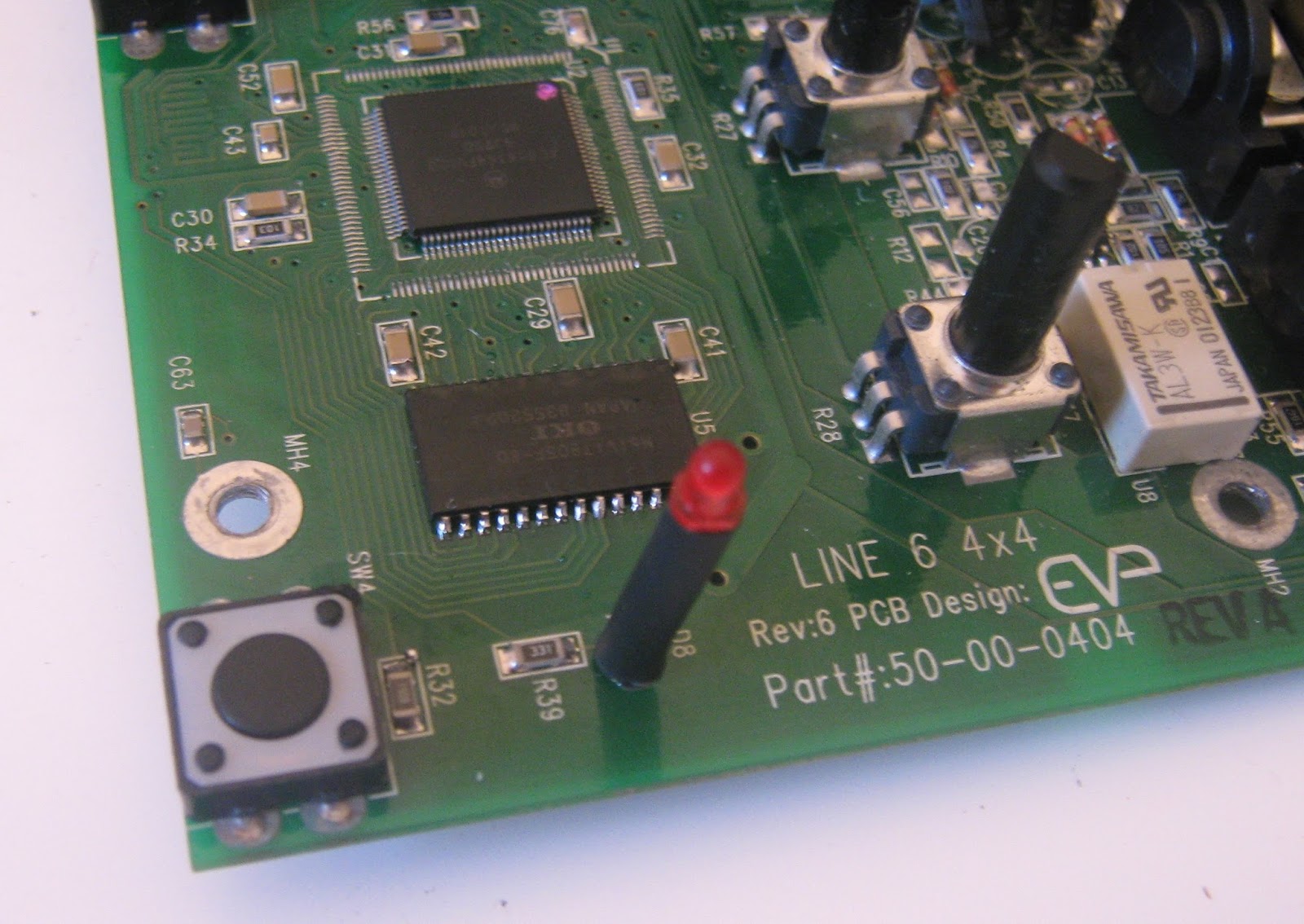
| Main board |
There is quite a lot of info on this series online. This thread at freestompboxes.org has a complete service manual that includes full schematics and BOM for most revisions http://www.freestompboxes.org/viewtopic.php?t=23282&p=256501 for anyone who wants to play along.
All the pedals in this series are built on the same PCBs and have the same housings. The differences come down to which parts are populated (the DM-4 and AM-4 are mono only) and which firmware is in the EPROM chip. There's an NXP DSPB56364 DSP doing the audio processing, an 80C32 microcontroller for reading inputs/housekeeping and a Cirrus CS4223 24-bit 48kHz audio ADC/DAC. The rest of the board is some CMOS logic gates for sequencing LEDs and relay switching and some reasonably complicated voltage regulators for power. Nearly all parts are available as replacements, except for the DSP which is discontinued but still for sale from surplus and grey-market sellers.
This board seemed to have power issues, as I couldn't find any voltage rails that seemed correct. The Line 6 power supply is 9VAC and the internal DC supplies are pretty convoluted. 9VAC is fed through a 3.6 V zener and 1N4002 diode and connected to a MAX887 buck regulator (U14) producing 3.3V. The 3.3V supply powers some of the digital side, and also supplies a MAX660 voltage doubler (U20, giving 6.6V output), which is further regulated by an LM3480 5V regulator (U21). Finally, a LM2664 charge pump inverter (U15) produces -5V. The + and -5V rails are used for opamps throughout and 3.3V and 5V power the digital ICs. There's a very good post at the diystompboxes forum covering troubleshooting of these supplies http://www.diystompboxes.com/smfforum/index.php?topic=41142.msg297051#msg297051
" ..so the most likely suspects are
1: 3,6v Zener ( D16 )
2: MAX887 ( U14 )
3: MAX660 ( U20 )
4: LM3480 ( U21 )"
It's worth noting that the MAX887 has a shutdown pin that is switched by the input jack. The voltage regulators won't start up unless you have a cable in the input jack.
I had no 3.3V supply so I suspected the MAX887 and the diodes at the input. I replaced D11, D12 & D16 and applied power. The MAX887 immediately blew a hole in it's case and started smoking.

I removed the MAX887 and R49. R49 measured good out of circuit so I put it back. I tried powering up without the MAX887 and C40 (1000 uF) exploded. After removing it I had a close look at the board. There were some jumpers from battery contacts to the DC jack that look like a previous repair attempt. There was another jumper on the topside from the DC jack that I removed.
 |
| WTF |
There are 4 testpoints on the main PCB that can be used to validate if things are working. When viewed on a scope, MCLK should show a 12 MHz clock signal, SCLK a 3 MHz clock, LRCLK a 47.8 kHz clock and ADC and DAC should show data changing at around 1 MHz. DAC will only show data if you have a cable in the output jack.

DL-4 Conversion
Ok, so the difference between pedals in this series is just what software is loaded, so can we convert one to another by swapping ROM chips? I tried the EPROM from the scrap DL-4 board (marked DL-4 V1.3) in the MM4 and it doesn't work, the pedal is non-responsive. Comparing the two boards it looks like the only difference is that U5 is not populated in the MM4. This makes sense, U5 is a 16mbit DRAM. The DSP has a small amount of RAM that can hold enough audio for effects like flangers, but the DL-4 has long delays and a 14 second looper so some extra memory is needed. I attempted to transplant U5 from my scrap DL-4 to the working MM-4. |
| U5 on scrap board. Pots and some caps had already been scavenged. |
 | ||||
| U5 desoldered. |
U5 came off with hot air after a few minutes. Unfortunately the two boards are of slightly different revisions and the footprints for U5 are different, so this was a tight fit on the MM4.
 |
| MM4 prepped for populating U5. |
 |
| U5 soldered. |
So it seems you can convert these pedals as long as the memory needed for the delay is present. I dumped the contents of both chips to PC. I also have a dump of an FM-4 I got online, but all of the PLCC chips in these pedals are one-time-programmable and can't be overwritten. I'll have to order some EEPROMS to try the FM-4 firmware. If anyone has dumps of the AM-4 or DM-4 please get in touch, it would be fun to try these, even if just for completeness.
I think it should be possibly to modify any of these pedals to switch out firmware and reset the DSP to go between DL-4/FM-4/MM-4/whatever at will, possibly on a footswitch.
Excellent work!
ReplyDeletehi - do you know where the preset memory is stored. if not i will have to get the scope out and look. also could i have a dump of the mm4 eprom file,. just so i can see what they sound like or run with both just a switched select/reset to get the next effect. good work thanks
ReplyDeletePresets are stored in U5, AK93C45, a 1k serial EEPROM. I haven't played much with recording presets and loading them on different firmwares but it seems to work fine, I think only the pot positions are saved.
DeleteI have thought about switchable firmware, the best way is probably removing the PCB socket and adding a PCB to hold an EEPROM in a cheaper package and some logic to do switching and reset. Switching preset memory would mean running a few wires to U5 and taking over enable signals.
I will probably post the ROM dumps soon, I've repaired a couple more of these and want to write about those.
This comment has been removed by the author.
ReplyDeleteNo, I haven't tried that. Sounds like it should work, let me know if it does.
Deletei meant enable pin 3
ReplyDeleteHi there it all works just fine.
ReplyDeleteI have a footswitch that selects between the chip selects. this foot switch also drives tri colour LEDS replacing the red ones . just so you know which memory bank you are in. SO 6 totally different echo settings. this I guess would be the same for the mm4 etc. only difference being you get 8 different presets. hope you are well Adam
Hi Adam, nice job. Are you using a counter to select the memory bank? Or just toggle between two chips?
DeleteHi krivx
ReplyDeleteI just used a switch.. the chip selects are active high, so I had a 4k7 pull down attached to each chip select, and a switch just switched the select from the processor either to this or to that. the rest of the switch then drove the lights. I wish I had copied this down before putting the lid on as this is from memory. but there were no other components other than extra memory switch two resistors. I soldered the memory chip right on top joinign all legs apart from chip select/enable pin. I cut the track that joins this to the processor , so then the three wires ( two selects and one processor drive) + a ground local to this , were taken to the switch. The lEDS were a totally seperate circuit. hope this all helps Adam.
I guess memory access is only done while switching or saving presets? You can't get corrupted data by changing chips while the pedals is running? That's very cool if so, I'm surprised those kind of mods aren't more popular.
DeleteHi again, As I now have two DL4's do you have the MM4 Eprom code. If so could I have a copy please. Just so I could change one of the DL4's into a MM4
ReplyDeleteThanks for any reply.
Adam.
Also just picked up a cheap broken DM4 which I hope to get going soon.
I remember saying I could post these and I forgot to do it. Sorry, I will try to get these uploaded in the next couple of days.
DeleteIt took me a while, but I have posted these.
DeleteThat is correct. Checked on the scope and memory access is only during switching. if you switch while changing chips I guess the pedal can get confused but this doesn't corrupted memorys as writes only happen during a save of a preset.
ReplyDeletedo you have a dump of the mm4 code I could try out?
ReplyDeleteThanks
a
AS for this.....
ReplyDelete"I'm surprised those kind of mods aren't more popular."
So am I..
It seems by far one of the best mods to do.
I forgot to say.. that best best best mod to do to these pedals is to convert to standard BOSS input.
ReplyDeletechange power connector, move some parts around two wire links and the DL4 draws 130mA max from 9V DC and the max887 chip is within spec so no more falures. I think they just made it 9VAC to sell power suplies etc.
Interesting mod - would you mind elaborating on this in further detail?
DeleteHI
ReplyDeleteI sure can. do you have a Email address where I could send pictures schematics? or can I upload pictures here. I just can't seem to find how to.
This comment has been removed by the author.
DeleteGreat! I'd think it would benefit everyone if we could find a way to post it here. You can upload your images to tinypic.com or imgur.com and just link them in a reply here :)
ReplyDeleteHi, I'm also working on switchable firmware for the Line6 4x4's
ReplyDeleteI have successfully done Digitech xp-all mods and this has to be kind of the same thing.
Adam, did you used 2 separated eproms or did you burned both firmwares in a same chip? Can you send me pictures? Thanks! gui113m (at) hotmail.com
Oh, I forgot. Krivx, I can provide you FM4 V1.0 firmware if you want. Cheers!
DeleteHi Gui113m, thanks but I have the FM4 image and posted it in a recent blog entry.
DeleteHello, my 3.6v Zener diode is fried. I want to replace it but i see different wattage when i try to order one. Can you tell me exactly which one to get, please?
ReplyDeleteChris
Chris, sorry for the late response. You want 1W or higher, I would try to get a 2W or 3W if available.
Deletedo you still have problems?
ReplyDeletegreat site. I have a faulty DL4, powersupply voltages are ok. switches are changed. It boots but "hangs" on first patch selected. and cant be changed, no sound is coming through... Ive swapped the Eprom from a nother unit, same thing.
ReplyDeleteany ideas are welcome.
Carsten, Denmark
I would get the service manual from the link in the post and go through the test modes - a failing test may point to you a failing component
DeleteSeems like you have some experience so Ill ask you- my Dl4 powers up, all switches and pots work, it passes true bypass signal, but doesnt pass anything when switched on. I've tested the power supply and the voltages look good- I tried the test mode as found in the repair guide but it wont let me get past test #9 for some reason- I cycle through the tests and it goes from #9 to #1. So I dont know about that.
ReplyDeleteAgain- voltages are fine through the board- the board looks perfect- no corrosion of any sort- I havent done a signal test, because that seems like a beast.
Any ideas on what I should replace first? the eprom (it 'tested' fine but i dont know), the adc/dac, dram?
Thank you for any direction to go from here!
ReplyDeleteI suggest the electrolyte caps. They try out. You have to change them all, but if the power supply is fine, then I don't know. I have one in the drawer with similar fault...never got around to fix it
ReplyDeleteHey, do you have / or do you know hot to get the firmware for the DL4 eprom? I cant find anywere to buy a new eprom, so im trying to flash a brand new chip. I need the rom firmware.
ReplyDeletehttps://falseelectronics.blogspot.com/2016/10/line6-dl4mm4fm4-firmware-images.html
Deletemy DL4 turns on the LEDs but does not generate sound ... I adapted another rewritable eprom
ReplyDelete