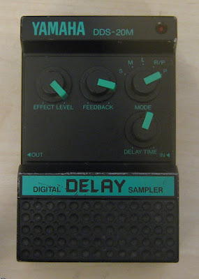
The mechanical design is a little different - all of the controls are recessed at a height below the footswitch and there is a "unibrow" along the top with the logos and LED.
There are no schematics and not a huge amount of info on these that I could find online, other than there was a range of pedals in this form factor. No signs of life.
After looking on the inside, I got the impression that someone else had attempted a fix. There was a resistor between the +9V and ground pads of the DC jack (?), the ground trace had been cut in two places for some reason and a wire had been soldered in to replace it. I can't see why the resistor between 9V and ground would be needed for anything other than wasting power, so I removed it. I also found that the ground from the DC jack was not connected to circuit ground. Adding a jumper was enough to get this to fire up with a DC supply, but not with a battery. It's possible that the resistor was originally connected between jack ground and circuit ground but as it was several kilo-ohms a wire would be a better solution.
The pedal uses a 2 board design, connected together with wires. Both are single-sided PCBs that look like a phenolic paper material and no through-hole plating anywhere. This is pretty typical for 80s Japanese electronics but it can mean that any board-mounted hardware can be fragile as there is only solder on one side of the board anchoring it place. In this delay, the output jack had taken some force (probably a cable was stepped on) and the pad to the jack tip had broken, this had to be re-soldered to get an output signal. One of the PCBs has most of the analog parts, the inner one has the digital controller and the pots and rotary switch.
 |
| 2 wires added and a diode replaced |
 |
| Analog board, component side |
The analog board has a 4066 for bypass/effected switching, 5534 opamps, a Motorola M5218 audio pre-amp (I have only seen this part in Japanese pedals, I think the original Boss DS-1 used something like this), μpc1571 compander (NEC's NE571 clone) and the chip in the bottom left corner is an LM311 comparator. The comparator is forming part of a sigma-delta ADC with the digital controller, much like the Boss DD-2 and the Digitech PDS series of delays.
 |
| Bizarre vertical component assemblies |
I thought the parts marked "< RIVER < RIVER" were SIP ICs, but they are actually components standing vertically! They seem to be clamped together at the top. I don't know if there was automated machines to produce these assemblies or if they were re-used in other designs but it's surprising that this was cheap enough to be worth the effort.
 | |
| Digital board |
The digital controller is an "M654131". No info on this, probably a Yamaha custom. Maybe they used it somewhere else in a different product. I don't have any pictures of the back side of this board so I don't know what type of memory is used. It looks like there are two 9-pin SIPs connected straight to the controller so I would guess 2 64k DRAMs, assuming this is an 8-bit delay.
It sounds great. I like that these early digital designs use companders and have simple master clock signals. It's like a holdover from the days of analog delay designs. This one can pitch-shift the delay signal smoothly, unlike some more modern delays.


I had a couple of ideas for how to program in the operation of the caps lock key and its LED. Stream Smart TV box
ReplyDeleteI love this delay pedal, the self-oscillation is as good as any analog delay
ReplyDeleteI have one of these pedals that is not working and has some similar problems. Like you, I found a broken connection on one of the jack connections. That has nearly got it working (on battery). Is the diode that you replaced the one marked as D2 on the board. What component did you use - is it critical?
ReplyDeleteJust got one of these. Great pedal. Thanks for the write up!
ReplyDelete