Thursday, 31 January 2019

Way Huge Aqua Puss MK II

I don't think I've ever looked at anything by Way Huge before. This is a modern version of the Aqua-Puss, and Jim Dunlop acquired Way Huge in 2006, so I expect it to be similar to the current Dunlop and MXR stuff.

This one would light it's LED when switched on but wouldn't pass a signal.


The insides are really nice, and very easy to disassemble. There are three PCBs - one just breaking out the switch contacts, one SMD board for input/output and switching and one through-hole board with the effect guts. They probably re-use the two smaller PCBs for all of the pedals in this size of enclosure.

Interior

The upper board has a CD4013 dual flip-flop, a CD4093B quad NAND gate and a relay to handle the bypass. The manual says the pedal has "AC protection", I don't know if this is just a series Shottky diode or something more sophisticated. There are some opamps and what looks like a IRF7606 Mosfet in a micro-8 package, that could be doing some power switching in case of reverse polarity or an AC supply connected. Relay is a EA2-5SNJ, similar to what's in a DL4.

I/O & switching board component side

Jack side

The delay board a V3205 BBD and BL3102 clock generator, SA571 compoundor and LF353 opamp for input and output buffering. Freestompboxes.org has the full schematic, it's not too complex a delay and similar to a DM-2/DM-3.

Pinout of the 8-pin connector is as follows (taking the pin with square PCB footprint as pin 1)
  1. 9V
  2. Ground
  3. LED
  4. Bypass switch
  5. Input signal
  6. Output signal
  7. Relay coil
  8. Relay coil 
The relay coil contacts are probably only broken out so the small PCB can be connected to a test jig, the main board doesn't route them anywhere.

Delay board component side

Delay board back side


I couldn't tell if the relay was actually switching, as it was hard to hear it click over the sound of the footswitch. When I disconnected the foot switch board and triggered the switch with some wire I could hear the relay clicking, so the switching logic was probably good.

After hooking up a test signal and oscilloscope I could see that the input signal was reaching the first opamp stage but there was nothing at the output pin. I desoldered the LF353 and replaced it with a socket and a TL072 for now.

Removed LF353

Now I had a clean signal in bypassed mode, but no delay. No switching waveforms on the BBD on the oscilloscope. No power at either the clock generator or BBD either. The schematic shows an NPN transistor/diode voltage regulator for these chips, I found that the 2N3904 transistor was blown to shit! After replacing with a new 2N3904 it regulator to around 7.4 volts. I'm not totally sure why this is needed as the BL3102 & V3205 should be happy to run on 9V, this may be a holdover from using older BBD chips. (Update: it turns out that there are multiple V3205 datasheets online, with conflicting information. According to Coolaudio, the max Vdd for a V3205SD is 8V).

Epoxy case blown off voltage regulator pass transistor. I don't know how I missed this.

I could now see clock signal at the BBD which varied with the delay knob as expected, but still no delay. I could see an input signal at pin 11 of the SA571 but nothing at the output on pin 10. I borrowed an SA570 from PDS delay pedal and this brought back the delay effect. Sounds great but not too different from other analog delays I have.

So: dead 2N3904 regulator, dead LF353 and dead SA571. I'm guessing this was fed too high a voltage from the wrong power supply. It's running happily 24 hours later with a new SA571 so this will probably go up for sale on Reverb pretty soon.

Friday, 7 December 2018

Silvertone Bass 35


This is a cool little solid state bass amp, I'm guessing dating to the 60s. No idea if Silvertone manufactured this, or if it was a rebrand, as there is very little information about this model online.

Solid State Bass 35

No output signal. Only 5 transistors, so surely this would be easy? Instead of getting through this quickly I had it for several months, only looking at it when I had a few minutes to spare. If I had more space to work with this could have been much faster and easier. This has been a trend with physically large gear, I should really think about learning a lesson and getting a wide bench and keep it clean somehow.

Single sided phenolic PCB

Full of cracks and mild corrosion

This amp has been worked on in the past, and has some of the electrolytics replaced. It was also dropped on it's faceplate at some point in the past, and the phenolic PCB has cracked. The ground pour is broken in a few places and it has been bridged with solder.


Original output transistors.

Most of the transistors appear to be branded with house-markings, as I can't find any references to their part numbers. I initially though output transistors were bad. They are marked "761" and "CG121", no info on these. One seemed to have a very low Vbe when measured with a DMM diode mode, which looked like a shorted junction. The TO-3 pinout is fairly standard for transistors, so I was assuming all cases were collectors. Collectors voltages were +35V and 0V, so I made guesses as to which output transistors were NPN and PNP types and then replaced with new 2N3055 and MJ2955 in TO-3 packages, new mica washers and new thermal grease.

Dead bass control/driver transistor

After tracing the signal through the amp with a scope I found that nothing was getting to the output transistor bases. Nothing was passing the third transistor that drives the output transistors and implements the bass control. It was marked "5981 274 S6721", no idea. I desoldered this part and found that it was dead, completely shorted leads. I replaced this with a BD139. Based on a guess of the polarity of the original and the size of that package I thought this should handle the current requirements. With the BD139 I got some life, there was an output signal sometimes. Turning power on and off would sometimes get it working, sometimes it would stop. I found that there was a high-frequency oscillation at the output stage, if it drifted in and out of oscillation then things would work. Capacitors from collectors to base pins fixed this, values were just picked experimentally.

It still didn't sound right. There was an odd overtone riding on top of the signal that couldn't really be dialed out, though it sounded better at higher volumes. Another parasitic oscillation? Bias issue?

Around this time I bought a Peak Atlas DCA 55 Semiconductor tester. This is a very useful tool for testing transistors and diodes, and will also attempt to identify parts based on I/V characteristics. I still had the original TO3 power transistors, so I tried them out. One read a Vbe of 0.19V but was identified as PNP germanium, and working. I had assumed Vbe this low was a problem. After putting the old transistors back into the amp with new grease it sounded great, not very clean but not totally distorted either. The replacement silicon part wasn't biased correctly, the odd sound was probably some crossover distortion.


There is a diode from the base of CG121 which is probably used for biasing, I would guess that this is also germanium and modifying the amp to use new silicon transistors would involve replacing this as well.

The replacement BD139 runs quite warm, but not so much that I would worry about heatsinking it yet.

Here are measurements of the originals, they are surprisingly mismatched. This may not be a push-pull design at all.

7671
NPN silicon
hfe 108 @ Ic 2.5 ma
Vbe 0.643V

cg121
PNP germanium
hfe 59 @ Ic 2.5 mA
Vbe 0.190V
Ib 4.781 mA


Hopefully this is good for another 40 years.

Thursday, 22 November 2018

Red Panda Particle

It's been a while. I have been doing repair jobs and not posting them, so I will try to clear the backlog.

I bought a non-working Red Panda Particle granular delay for a decent price. This is fairly well documented as a Spin FV-1 design, but the granular delay programs and pitch-shifting & randomised modes really drew my interest.


The insides are fairly simple - the FV-1, a 24LC32a serial EEPROM, a 74HC148 priority encoder (to decode the rotary switch and select which program to run) and a quad OPA4134 opamp. The "chop", "delay/pitch" and "param" pots are read by the FV-1, the blend and feedback controls appear to be done in the analog domain. This looks more or less like a reference FV-1 design, all the magic is in the program code.

The PCB layout is nice, pots and jacks are board-mounted and the DC jack is on a connector so the entire board can be removed or tested before installing in an enclosure. They use a PCB mounted spring to ground the enclosure, like the modern EHX designs, but this one seems to be contacting an oversprayed section.

Interior layout.

This pedal passed no signal in effected mode. I probed the OPA4134 and the first opamp that drives the mix control was stuck at near ~8V DC. After replacing the chip everything worked.

IC10 removed.


This is a really cool design, in that it's very different to nearly every delay I've used before. It is quite difficult to predict how the different modes will sound, and I think this would need some significant playtime to learn. Unfortunately this one came along at a time when I didn't have a lot of free time or desire to keep amassing pedals, so I have sold it on.

I did dump the EEPROM. Looking at it briefly with the excellent online FV-1 decompiler, each program looks to have disassembled correctly and makes some sense. I'm reluctant to share this, as this is really the only unique part of the pedal, and AFAIK it hasn't been cloned. If you have a genuine repair need (pedal with dead ROM) then get in touch, maybe I'll help. I may also revisit this and get it running on a different FV-1 board at some point in the future.

Thursday, 1 March 2018

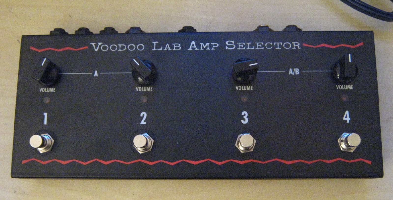
Voodoo Labs Amp Selector

 This is a 2 input, 4 output amp selector and A/B switch. One guitar can drive 4 isolated outputs, all with their own volume controls and ground lifts. There is some preset save/recall functionality, so I am expecting a microcontroller in here somewhere. This is exactly the sort of thing I would have loved to play with when I was renting a practice room and had access to lots of amps, but it will probably just be sold on nowadays.


Main PCB
No surprises on the insides - there is an P87LPC764 MCU reading switches and turning JFET switches on and off. A MAX1044 provides a -9V supply. The transformers are 6 pin devices with any labels or markings removed. There is one OPA2134 dual opamp, and a 24C01 serial EEPROM for presets.

Hacked in parts at the power input.
The back of the PCB has some factory bodges/mods at the power input - there is a series resistor and a capacitor added to the MAX1044 input.

The digital side seemed to work, everything lit up and it did switch signals, but there was lots of bleed between outputs and the volume was quite weak.

I know from experience that a MAX1044 will only tolerate ~10V input before dying, so I looked there first. The inverted voltage was measuring less than -1V. I desoldered the MAX1044 and replaced it - no change. There is a zener diode at the input pin which should limit the input voltage, I lifted this part out and now I had -8V and a working pedal.

Replaced MAX1044 (pictured here sitting crooked in a socket) and lifted diode D10
This diode was a 1n5239b (9.1V 0.5W zener) so I replaced it with a 1W part I had at hand. Now the negative voltage was pulled low again! It turned out that the cap across the zener that was added to the packside was leaking. It still measured 2.2uF but had ESR >5 ohm - this looks like a dipped tantulum part. I replaced with a similar electrolytic. It's not even technically needed, the cap is just stabilising the 9.1V zener clamp when it's conducting.

TC Electronics Nova Drive NDR-1

Programmable overdrive & distortion from TC Electronics. All overdrive/distortion parameters are controlled digitally, so presets can be saved and recalled, the order of the two circuits can be changed, they can be run in series or in parallel. All of this can be triggered by MIDI.


 TC did a Nova series of pedals and multi-effects units, but I don't think they were all built around a common digital design (like the Line 6 4x4 series). TC stuff is interesting as they have a history of high quality and targeting high-end markets and they tend to use fairly modern designs and parts. Unfortunately they don't seem to release much information or contract out any repair services, so I have not come across any modern TC Electronics schematics, either official or leaked.
TC were sold to Behringer in 2015 and their latest range of pedals look to be more standard stuff, a bit watered-down compared to the Nova series. I'll reserve judgement until I see one.
This series used a 12V power supply for some reason (why not 9V, like everything else?)
This Nova Drive started up but only passed a signal in bypass mode. The LED display and indicators did react to the knobs and to button presses, which at least meant that the digital section is working and the problem was likely in the analog end.

Top PCB (digital)
The build quality is really nice, they use a folded and tapped sheet metal chassis instead of cast box. There are two PCBs inside, the first is a "mezzanine" board with the encoders, buttons and displays. There is an Atmel ATmega168 and some '595 and '165 shift registers for digital IO. I'm pretty sure the ATmega is reading out pots and buttons and controlling something on another PCB to vary the effect parameters, as well as driving the LED displays and responding to MIDI commands. I would guess that this top PCB is probably very similar across all the Nova pedals. I am assuming the ATmega has some code-protection so I haven't tried desoldering and dumping it.

Lower PCB (analog)

The bottom PCB fills the whole enclosure - it has a bunch of opamps (presumably the analog overdrive and distortion circuits), DG441D quad analog switch ICs, switching power supplies, the MIDI optoisolator, a relay and a Cirrus CS3308. The CS3308 is a cool part, it's an 8-channel digitally programmable volume control. Presumably each channel is mapped to one encoder (4 knobs for overdrive and 4 for distortion) and the ATmega sets the levels over SPI or I2C. TC have used the +-5V version with 123 dB of dynamic range, which is kind of ludicrous for a distortion pedal.

Lower PCB, backside

U3 generates -12V from 12V input

All parts on this side are glued in placed before soldering

The bottom PCB is very parts-dense, but helpfully there are test points for all supply voltages. I found that -12V was reading very low and so all of the negative supplies that are derived from -12V were also missing. -12V appeared to come from a switching supply controlled by a CS51411 on the underside of the PCB, the circuit looks liked a close match to the inverting converter in the datasheet (Fig 25). The inductor was getting burning hot, so the switching IC was a pretty likely culprit. TC used a double sided load for this PCB, and parts on the underside are wave-soldered instead of reflowed, which means they are all held in place with a dot of red epoxy. Desoldering the IC took a lot more heat and force than I'm used to but it did eventually lift off. It still didn't work with a new chip, solid 12V DC across the inductor with no switching happening, which explains the heating. The SYNC pin did have a ~340 kHz square wave - I don't know if this was also present on the original chip. The huge number of test points on the back of this larger PCB suggests TC use some kind of bed-of-nails jig for testing during manufacturing.

Around this time I held my hand over the board when powered up and found another hot spot. One of the two DG441D switch ICs was also running hot, so I desoldered it. This part does run off +12V and -12V rails, so it may have killed the -12V supply when it failed.

There is another switching power supply using a L5970D controller - this one is generating 3.3V for the digital parts and was working correctly.

As I knew there may have been a short from -12V to ground or some other supply, I wanted to see if I could completely isolate the CS51411 from the -12V supply and use an external power supply to provide -12V. I removed the output capacitor and the inductor. Using an bench supply wired to the board and providing -12V, the pedal worked. Surprisingly, it pulled over 100 mA which seemed very high for some opamps and switch ICs so there may have been some other damaged part on that -12V rail.

The series/parallel switching did not work, only series mode passed a wet signal. This confirms the DG441Ds are routing the signals into series or parallel combinations, one of them was still missing. A new IC here restored all modes.

The CS51411's inductor measured 33uH out of circuit which seemed correct. I decided to try swapping it with this part, which fixed all the power supply issues. I am guessing that the old inductor got so hot that it reached it's curie temperature and it's magnetic properties changed (??) The new part runs cool. Looking again at the CS3308 datasheet shows it pulls 36 - 50 mA on both positive and negative analog supplies (!), which explains the high power consumption seen earlier, and why the pedal originally shipped with a 12V supply rated for 400 mA. This chip does run noticeably warm, but the power consumption matches the datasheet figures. I can only guess that power consumption is targeted  high to help lower noise and increase dynamic range. For a distortion pedal a low-power version with poorer specs would probably be a much better fit. The pedal will actually work with 9V input, and will generate a -9V supply instead, but will need a beefier supply than is usually seen on pedalboards.

All good again.
I broke the ribbon cable connecting the two boards when I was working on this. I just replaced it with individual wires - I would really like a tool that strips ribbon cable so I could just buy a small reel, if anyone knows of one please let me know.

Sunday, 18 February 2018

Electro-Harmonix Pitchfork

I don't know if the PitchFork exists alongside the POG series for market segmentation reasons or as a direct competitor to the Whammy pedal. Whatever the reason, EHX have another polyphonic pitch-shifter/harmonizer with a slightly different feature set, and strangely, a lower price. This one will add a harmonized voice at a selectable interval, at a higher or lower pitch or both. You also get a clean blend. There is an expression pedal control and the footswitch can be set to work in a momentary mode, which suggests Whammy style punch-ins, but it does POG style octaves as well.


The insides are very similar to the newer POG pedals, with an Analog Device Blackfin DSP (ADSP-BF592) and a AKM AK4552 24-bit/92 kHz ADC/DAC. There is also a 25L1005 serial flash with the program code - I did end up desoldering and dumping this in case I come across another and need it.

Picture taken after repair - clean.


Taken before repair - PCB appears cloudy

This one would not show any signs of life, and turned out to be shorting out my power supply. The reverse polarity diode (D2) on the back of the DC jack measured as a short circuit, so I removed it and the pedal worked! For about 10 or 15 minutes. Something else between 9V and ground was shorting.

11-detent "Mode" pot showing some stains
After a little while spent probing around and occasionally getting a short burst of life followed by nothing, I noticed that one pot had some corrosion on the back sides. I desoldered it and wire-brushed it until it was clean but couldn't figure out how this would be the cause of the problem. The corrosion was probably from some liquid spilled into the pedal.

I could see some kind of dirt at the power jack, so I removed it and things were then pretty obvious, some liquid had been trapped between the jack and PCB and had corroded the board, causing intermittent shorts.

Original DC jack

..and underneath the jack
Some scrubbing with PCB cleaner and a new DC jack later and it is rock-solid. The rest of the board was cleaned as well, what looked like cloudy flux residue was probably stains from dried liquid.

This is a pretty clear case, something was spilled and the pedal was never taken apart and cleaned afterwards. If it had been looked after at the time then no parts would have needed replacement. Underneath DC jacks and instrument jacks are probably the worse places for this, as they can trap liquid easily.

Thursday, 1 February 2018

EBS ValveDrive

This is another 2017 leftover, I want to write it down before I forget it.

EBS's ValveDrive is a valve overdrive/preamp that uses a single 12AX7 dual triode. This is the original version, there is a newer model that adds a balanced XLR output and has an internal switching power supply.
 The "vintage" circuit is similar to various Fender Baseman preamps, the "modern" setting adds some diode clipping - the original schematic is available at Freestompboxes.org. It uses a 12 VAC power supply and has an internal 12 VAC transformer wired "backwards" to supply the high voltage for 12AX7 plate. This used to be a very popular pedal with bass players, especially as the high voltage supply means it can get really loud and will happily drive a standalone power amp. Maybe it is not as fashionable right now, I don't see them as often as ~5 years ago.

Like nearly everything that comes across my bench, it doesn't work.


After verifying that my 12 VAC supply was working, I removed the top shield and looked at the valve. No wonder it does nothing, the vacuum has escaped from this one.

I put in a Jet City RetroValve that I keep around for testing, and still nothing. After pulling the valve and probing the socket I measured 0V at the plates - something wrong with the high voltage supply. The heaters are getting 12VDC, so low voltage power should be OK.

A leak has developed somewhere...

The build quality is very good, a nice folded steel enclosure and multiple PCBs connected together with ribbon cable (switching signals) and runs of coax for the audio signals. This was probably expensive to manufacture but it's hard to kill and convenient to work on.


The high voltage transformer is on the lower left of the topside of the PCB. The surface mount fuse on the backside is not blown, but the transformer looks weird, as if it had been re-soldered or replaced. The output winding only measured around 0.5 VAC with the power supply connected.

Transformer pins are not coming through the plated holes...

Additional holes drilled in PCB...
Once it was desoldered, it was obvious why things looked strange. The transformer pins were not going through the plated through-holes, instead someone had drilled holes in the PCB (!) and bridged over to the pads with some bus-bar to make the transformer fit. The low voltage measured at the transformer made sense now, scaling 12 VAC to 230 VAC is a roughly 19.16 ratio. If the transformer was scaling 12VAC down by the same ratio I should get 0.6 V AC, which is pretty much what I had measured.

I reinstalled the transformer the other way round and now measured 230V AC, and 400+V DC at the valve plate with no valve installed. With a new valve installed, this dropped to around 350V, and everything worked and sounded great. The original filter capacitors were only rated to 400V, so I replaced this with 450V rated Nichicons in case this was ever left running with a dead or missing valve.

The part number on this transformer is slightly different from the schematic's part list, and obviously the footprint is different as well. My guess is that someone attempted to replace the transformer, installed it backwards, and then gave up and sold the pedal on. The slightly higher plate voltage(~350V vs 300V) is probably due to small differences between transformers.