Monday 25 April 2016

Line 6 MM4 Repair and DL4 Conversion


I think these are fairly well known. The big 4-switch pedals have been very successful, especially the Big Green Delay (DL-4) which was something of a game-changer in popularizing live looping. The basic idea of the series was large, robust floor units that grouped Line 6's modelling technology into different categories bases on effects type. This is the "Modulation Modeler" and does chorus, phaser, flanger, tremolo etc. The FM-4 did filter effects, and apparently there were Amp Modeler (AM-4) and Distortion Modeler (DM-4) units that didn't sell well. I guess the people buying these pedals didn't want Line 6 POD-style sounds, and everyone else saved some money and just bought PODs.

This is a beat-up unit I got from eBay, sold as not working and missing the footswitches and knobs. It doesn't seem like a lot of people are buying these as projects, despite used units holding their value very well for a late 90s digital effects (the DL-4 especially). You can see why: digital, surface mount, fairly complex.

Backside of the board just has a socketed EPROM
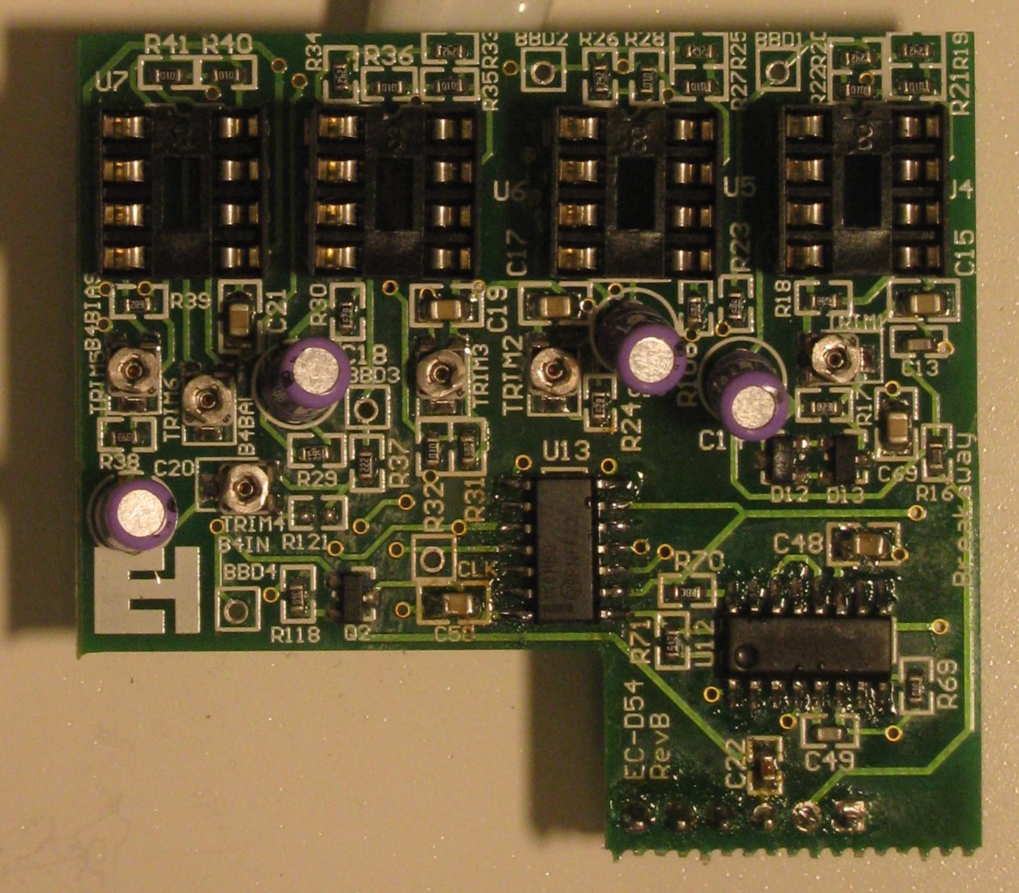
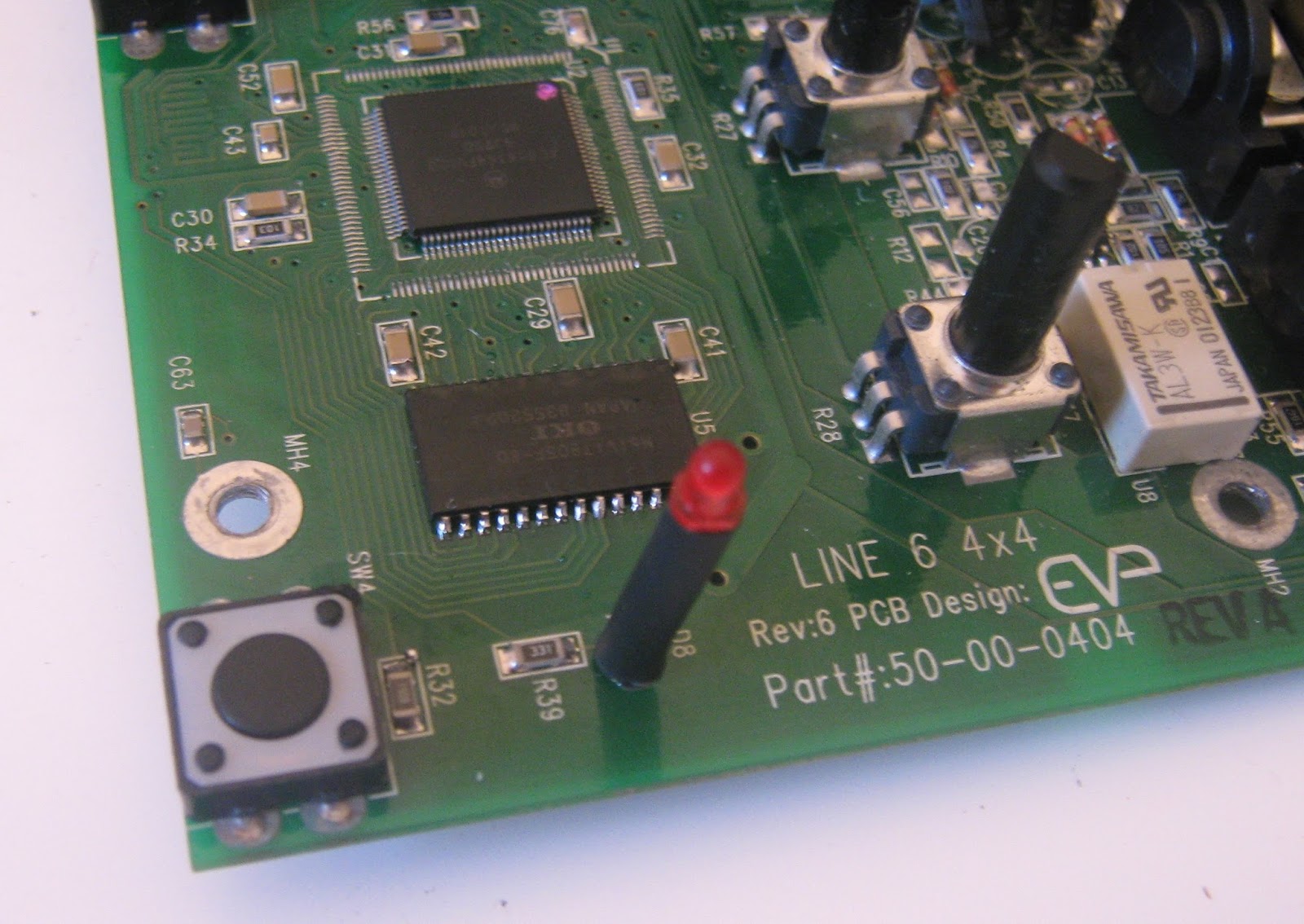
Main board


There is quite a lot of info on this series online. This thread at freestompboxes.org has a complete service manual that includes full schematics and BOM for most revisions http://www.freestompboxes.org/viewtopic.php?t=23282&p=256501 for anyone who wants to play along.

All the pedals in this series are built on the same PCBs and have the same housings. The differences come down to which parts are populated (the DM-4 and AM-4 are mono only) and which firmware is in the EPROM chip. There's an NXP DSPB56364 DSP doing the audio processing, an 80C32 microcontroller for reading inputs/housekeeping and a Cirrus CS4223 24-bit 48kHz audio ADC/DAC. The rest of the board is some CMOS logic gates for sequencing LEDs and relay switching and some reasonably complicated voltage regulators for power. Nearly all parts are available as replacements, except for the DSP which is discontinued but still for sale from surplus and grey-market sellers.

This board seemed to have power issues, as I couldn't find any voltage rails that seemed correct. The Line 6 power supply is 9VAC and the internal DC supplies are pretty convoluted. 9VAC is fed through a 3.6 V zener and 1N4002 diode and connected to a MAX887 buck regulator (U14) producing 3.3V. The 3.3V supply powers some of the digital side, and also supplies a MAX660 voltage doubler (U20, giving 6.6V output), which is further regulated by an LM3480 5V regulator (U21). Finally, a LM2664 charge pump inverter (U15) produces -5V. The + and -5V rails are used for opamps throughout and 3.3V and 5V power the digital ICs. There's a very good post at the diystompboxes forum covering troubleshooting of these supplies http://www.diystompboxes.com/smfforum/index.php?topic=41142.msg297051#msg297051

" ..so the most likely suspects are
1: 3,6v Zener ( D16 )
2: MAX887 ( U14 )
3: MAX660 ( U20 )
4: LM3480 ( U21 )"

It's worth noting that the MAX887 has a shutdown pin that is switched by the input jack. The voltage regulators won't start up unless you have a cable in the input jack.

I had no 3.3V supply so I suspected the MAX887 and the diodes at the input. I replaced D11, D12 & D16 and applied power. The MAX887 immediately blew a hole in it's case and started smoking.


I removed the MAX887 and R49. R49 measured good out of circuit so I put it back. I tried powering up without the MAX887 and C40 (1000 uF) exploded. After removing it I had a close look at the board. There were some jumpers from battery contacts to the DC jack that look like a previous repair attempt. There was another jumper on the topside from the DC jack that I removed.

WTF
After buzzing out the connections from DC jack to the voltage regulators I found a burnt track from the input choke (which is not populated) and D16. Maybe this was an attempt to fix that? I have no idea. I am lucky to have a spare DL-4 parts board courtesy of Moose Electronics Dublin (check him out https://www.facebook.com/mooseelectronicsdublin/?ref=br_rs). I swapped over the MAX887 from the spares board and jumpered over the damaged track. Now the 887 regulator circuit buzzed audibly. OK, it probably can't start up as C40 is missing. I swapped over C40 from the scrap board and now I had a correct set of voltages at each regulator. I pushed one of the switches and the relays clicked and LEDs lit up, working again. I have to use a screwdriver to push the switches until I can get some replacements but everything functions correctly.

There are 4 testpoints on the main PCB that can be used to validate if things are working. When viewed on a scope, MCLK should show a 12 MHz clock signal, SCLK a 3 MHz clock, LRCLK a 47.8 kHz clock and ADC and DAC should show data changing at around 1 MHz. DAC will only show data if you have a cable in the output jack.


DL-4 Conversion

Ok, so the difference between pedals in this series is just what software is loaded, so can we convert one to another by swapping ROM chips? I tried the EPROM from the scrap DL-4 board (marked DL-4 V1.3) in the MM4 and it doesn't work, the pedal is non-responsive. Comparing the two boards it looks like the only difference is that U5 is not populated in the MM4. This makes sense, U5 is a 16mbit DRAM. The DSP has a small amount of RAM that can hold enough audio for effects like flangers, but the DL-4 has long delays and a 14 second looper so some extra memory is needed. I attempted to transplant U5 from my scrap DL-4 to the working MM-4.

U5 on scrap board. Pots and some caps had already been scavenged.

U5 desoldered.


U5 came off with hot air after a few minutes. Unfortunately the two boards are of slightly different revisions and the footprints for U5 are different, so this was a tight fit on the MM4.

MM4 prepped for populating U5.
U5 soldered.
After soldering I tried the pedal with the original MM4 ROM chip (the socketed PLCC32 on the backside of the board) and it still worked as an MM4 with the extra memory added. I swapped in the DL-4 chip from the scrap board, and now it works as a DL-4 as well. I thought I might have gotten the pedal to lock-up in DL-4 use but this was probably because I didn't know how to use a DL-4 looper, it seems to work correctly after playing around for a half hour.

So it seems you can convert these pedals as long as the memory needed for the delay is present. I dumped the contents of both chips to PC. I also have a dump of an FM-4 I got online, but all of the PLCC chips in these pedals are one-time-programmable and can't be overwritten. I'll have to order some EEPROMS to try the FM-4 firmware. If anyone has dumps of the AM-4 or DM-4 please get in touch, it would be fun to try these, even if just for completeness.

I think it should be possibly to modify any of these pedals to switch out firmware and reset the DSP to go between DL-4/FM-4/MM-4/whatever at will, possibly on a footswitch.

Sunday 24 April 2016

Effectrode Delta-Trem

Something fancier than I normally get to play with. This is a stereo tube tremolo by "Audiophile Pedals" company Effectrode http://www.effectrode.com/delta-trem/delta-trem-in-depth/
2 12AX7s doing volume modulation, with controls for speed and depth of modulation as well as a "shape" control that blends between different LFO waveforms. This is an older 3 knob version, the current production model adds a "rhythm" control and changes the tubes to 12AU7.

I'm taking a look at this for a friend, apparently it was used with the wrong power supply and is now dead.


After opening it up, I'm surprised to see it's a mixed analog/digital design. There is a 8 pin SOIC PIC 12F5091 microcontroller acting as a switch-mode power supply controller and a second larger PIC 18F2620 reading the pots, switch, driving the LEDs and bypass relay and generating the LFO. Nice sealed Omeg pots for all controls. Switching FET is IRF740AS. There is also an IRF FL210 FET, I'm not sure what that one is doing as I didn't trace it out. The SOT23 transistors appear to be FMMT717 and FMMT617.

After powering the pedal with the correct 12V DC the 78L05A 5V regulator was not working correctly (high output voltage). I tried replacing it with a 78L05 in a TO-92 package but eventually found that the 1206 R470 resistor in series with the power jack was burned and was reading high (Mohms), limiting current to the regulator. A 1206 resistor is usually rated for about 1/4 W so I replaced it with a 470 ohm through-hole 1/4 W resistor. Still doesn't work. Whoops, "R470" means 0.47 ohm, not 470 ohm. I swapped in a 1.2 ohm resistor (closest value at hand) and it fired up.

It sounds very good, and gives a great variety of authentic amp-tremolo sounds. It doesn't really go beyond this into more extreme territory or do industrial-style hard chopping. There might be a slight volume drop, but that could be something inherent to all tremolo effects. Personally I don't know if I like tremolo enough to need an accurate tube version, but I guess I'm not really the target audience here. I didn't take apart the optocouplers as this is not my pedal but I am fairly sure they are just neon bulbs and cadmium sulfide photocells heatshrinked together.

There were a few things I didn't like. A microcontroller as a SMPS controller doesn't sit well with me. This increases development time and is another part that needs to be programmed before assembly, all for a controller that will have slower loop response than a dedicated controller IC, which could also cost less. It's also annoying from a repair point of view, if the microcontrollers are dead they can't be replaced without access to the firmware. I find this acceptable for the larger controller (but manufacturers, please provide people with binaries so they can fix their stuff!) but I can't see any reason why that 8 pin PIC needs to be programmable.

The SMPS provides the high voltage supply for the tubes, the 12AX7 cathodes are sitting at 251V. However there are no high-voltage warning on either side of the PCB, it's pretty easy to open the thing and touch a capacitor charged to a couple of hundred volts (ask me how I know this). The PCB is also unusually difficult to solder to and seems to suck heat away. I don't think there are any internal layers so I guess the copper might be extra thick? I can't see any reason why this would be needed. Finally, I feel that something in this class should be bulletproof in terms of surviving the wrong power supply. I'm not sure what was used when this thing died (probably an AC supply) but I have seen much cheaper pedals survive quite a bit of abuse without burning anything out.

I never had the correct power supply, but it needs a little over 600mA at 12V, maybe more if the tubes are starting off cold.

Electro-Harmonix Memory Boy #2


On to the second Memory Boy. I was hoping this would be the same problem again, but this one fought me.

After opening it, it was apparent that someone else had been in here before. The ribbon cable to the footswitch had been replaced with discrete wires and there was a large splash of solder hanging off an electrolytic cap on the main board. I have no idea if the ribbon actually failed or if the last person to work on this was just trying things, they tend to be reliable.

This one also had no wet signal. Power was OK, I checked the CLK testpoint and it also had no clock waveform. I replaced the 4011 hoping I was done, but still nothing. At this point I thought about replacing the LM13700 as well, but decided to trace out the daughterboard to see what it was actually doing. I remembered to take pictures of both sides of the PCBs this time.
Main PCB, backside

BBD board

BBD board, backside

It's not unusual when doing this that the problems reveals itself halfway through tracing out the circuit. In this case I found that I had no continuity between pin 2 of the header that connects the boards and pin 1 of the LM13700 (bias input), despite a track on the PCB clearly running between the two. I can only guess that the daughterboard was rocked on the header strip and this trace cracked. I ran a jumper wire between the header and the OTA and I had a clock signal again. Still no wet sound, which was worrying as it suggested the BBDs were bad. Fortunately, it seemed that the last repairperson also played with the bias trimpots, and after re-biasing each stage I had a working delay. Unfortunately, no schematics for everyone else, at least not yet.
Jumper wire from U12 to connector pin 2

This one sounds identical to the other, so unless I decide to try out some modifications I'll sell one (or both).

Electro-Harmonix Memory Boy #1

This was an eBay purchase that I bought as "For parts or not working". According to my account history I had been sitting on this for years before digging into it (yikes). I actually have two of these, the second unit was bought a year later and will be added here soon.

This is a 30 - 550ms analog delay (BBD) with modulation. Modulation waveform is switchable from triangle wave to square wave and rate can be set slow ("chorus") or fast ("vibrato"). An expression pedal can control delay time or modulation rate. The comparison to their legacy line is pretty obvious - this is meant to be a cut-down version of the Deluxe Memory Man, it has the same delay time but is missing controls for modulation rate and output level. I would guess that the Memory Boy and simpler Memory Toy were introduced to compete with MXR's successful Carbon Copy.

The pedal passes a clean signal but has no delay effect. Turn the blend control to 100% wet and it's completely silent. So input and output buffering and mixing are probably fine and the problem lies with the BBD circuit.

This is fairly heavily populated on the inside. This is the typical modern EHX style with pots, switches, footswitch, jacks and DC connector all mounted to a large PCB and then anchored to the case. A spring grounds the board to the enclosure. This style was designed to reduce assembly costs but it's hard to say if the quality is effected. It's a pain to get these boards out of the enclosure, I have been using a screwdriver to push in the DC jack but they get marred, so a plastic or wooden tool would work better. I like that the 3PDT footswitches is on it's own board with a ribbon cable, this switch will see the most force so strain-relieving it from the rest of the main board is a good idea.

It's a two PCB assembly, all surface mount ICs and passives. The main board appears to handle the input/output buffering, switching, modulation LFO and controls. The smaller daughterboard holds the BBD chips (4x BL3208A), the clock circuit and biasing and balancing trimmers.

Everything is analog, and apart from the BBDs EHX are only using common jellybean parts - SA571 companders, TL074, LM324 & 4558 opamps, LM13700 OTAs. These pedals should be repairable as long the SMD packages can be reworked (they can). The daughterboard is soldered to the main PCB with a 6 pin header strip, and there are some rubber pedal "feet" underneath to support it. I'm not a huge fan of this type of construction, anchoring the small PCB at one edge will allow it to lever and possible damage it. From what I've seen, the Memory Toy uses a similar construction method but the daughterboard is supported at two sides and is socketed instead of soldered. I desoldered the daughterboard to see if there were any backside components (none).
Main board - EC-D54 Rev. B

BBD Board -EC-D54 Rev. B. U13 was removed at this point.


After checking voltages at several ICs I started poking around with the oscilloscope. CMOS logic is used alongside analog ICs so 9V can be used everywhere, there are no voltage regulators onboard.
There is a helpful "CLK" test point on the smaller PCB that showed that I was getting no clock signal to the BBDs. There is a HEF4011 quad NAND-gate in use as an oscillator and an LM13700 configured as either a voltage-controlled resistor or capacitor to vary the frequency of oscillation, controlled by the modulation LFO.

I couldn't see any activity on the NAND chip (U13), so that was suspect. Lifting off the chip showed how it was connected on the PCB. I replaced the 4011 with a new one and the clock signal returned at the CLK test point. The clock frequency varies from about 5 kHz to 100 kHz. For 4 2048 stage BBDs this gives delay times from about ~40 ms to ~800ms, which seems correct. This means that bandwidth is limited to a few kHz at longer delay times,  which gives the characteristic dark sound. LFO is around 0.5 Hz in the slow ("chorus") setting.

After putting it back together it sounds great. I had some pretty bad clock noise at maximum delay time but this went away when I got it back inside the enclosure. Longer repeats are dark, and I don't hear much distortion (though I'm not sure if I would recognize if it was there). Modulation is nice, I find the triangle wave much more useful than the square. It doesn't do the clean repeats with strong attack that digital delays allow, but that's probably not what it's meant to do either.

I don't know why the 4011 failed. I did notice that the specific part used is only rated for ~1mA output current, it's possible that driving the input capacitance of the BBDs at high clock frequencies exceeded this (?) To be safe I used a MC14011 that can supply 8.8mA.

As for scope for mods, a dedicated modulation speed control would be nice. This can be done through the expression pedal jack but as it's only a single resistor in the LFO circuit controlling the rate I may attempt it there. It doesn't really oscillate when feedback is at maximum, so a series resistor with the feedback pot might have be jumpered to get it to break into oscillation.