Showing posts with label DL4. Show all posts

Sunday, 12 February 2017

Line 6 DL4 final fix

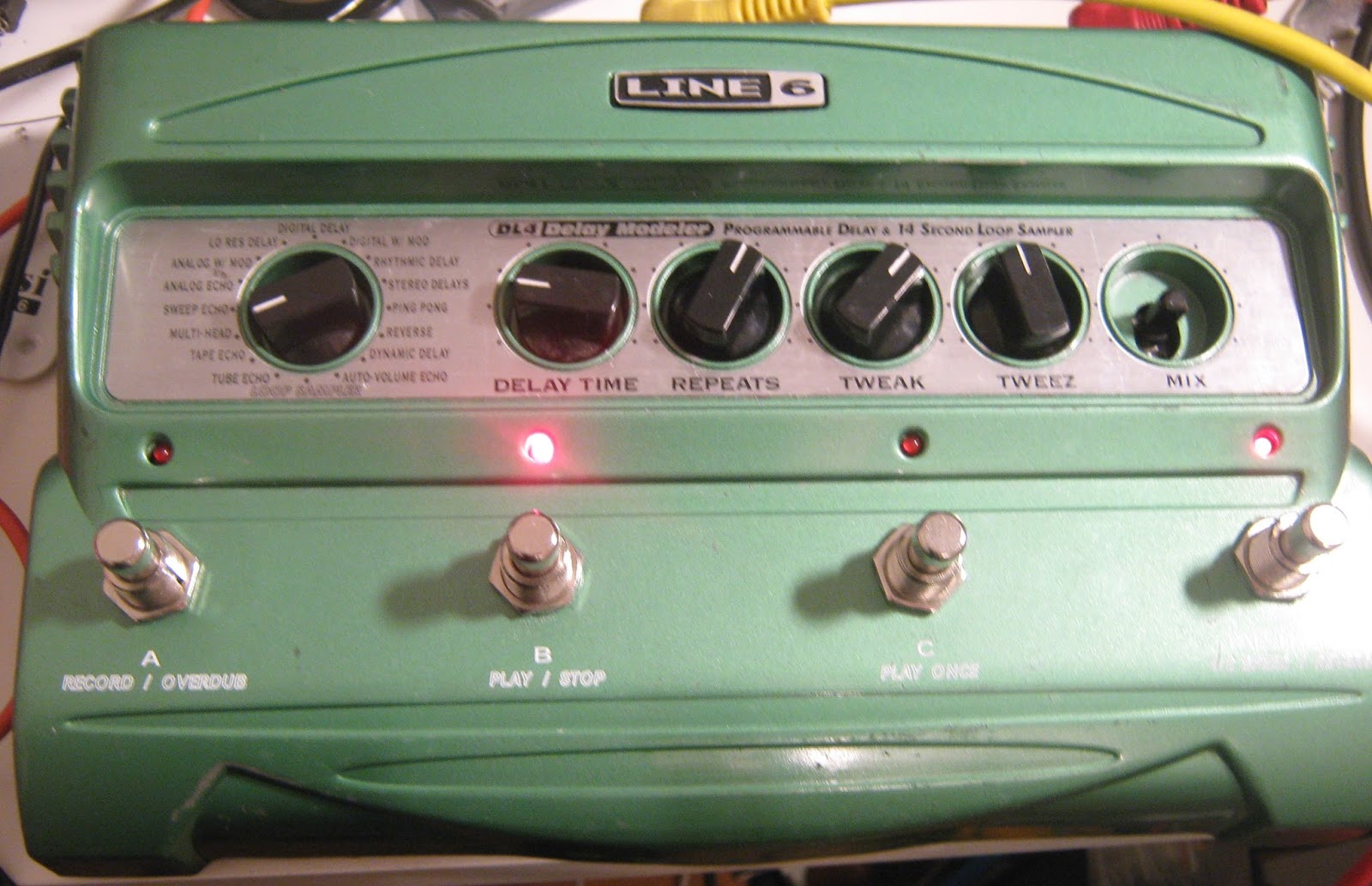
A short update on my DL4 that had come back from the dead but wouldn't run as a DL4.

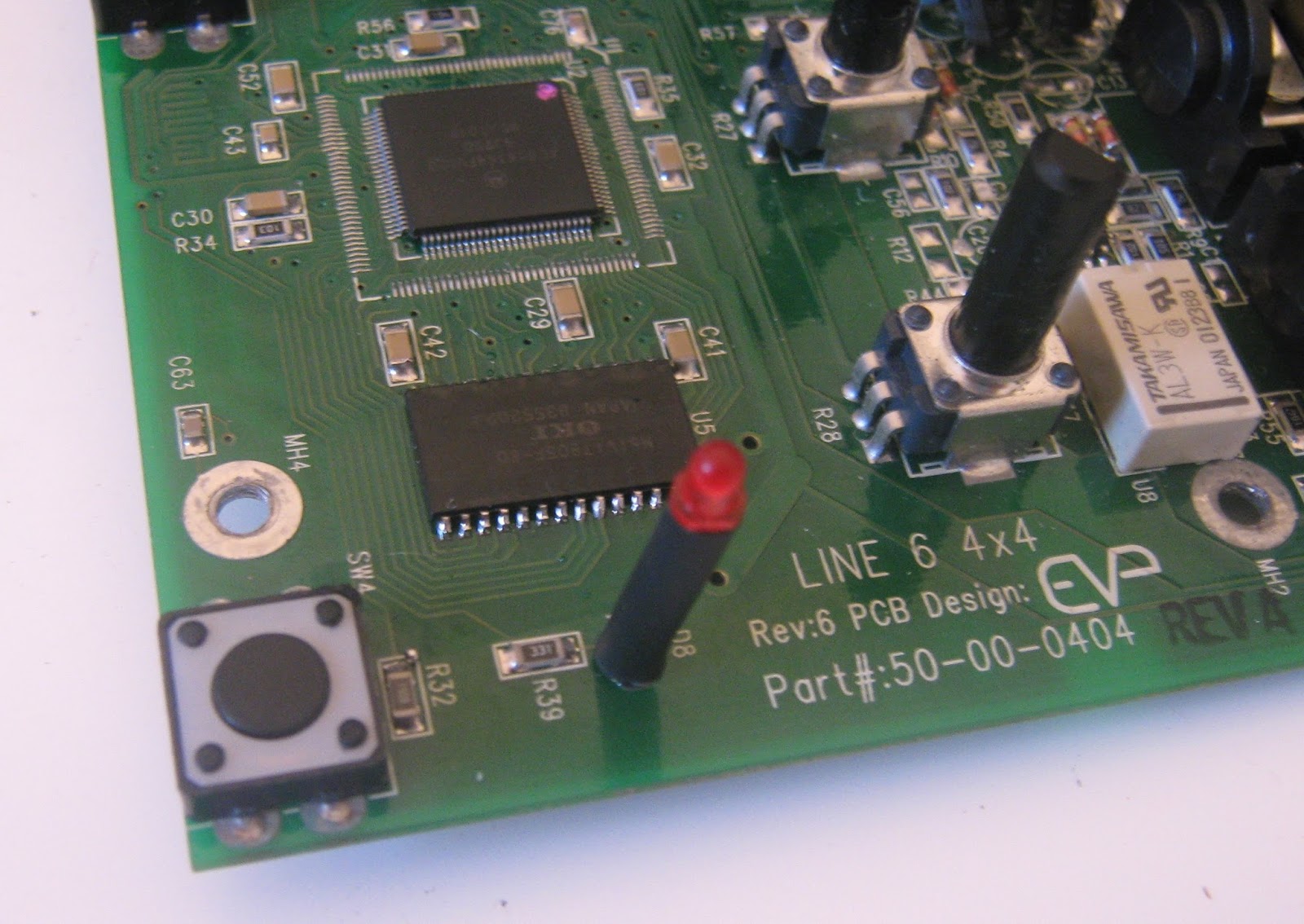
I went through 3 replacement DRAM chips and none of them worked. With all of them I got distorted noise instead of a delay signal. Yesterday I sat down with a schematic and beeped out every pin of the DRAM to the DSP. The RAS line (pin 45) of the DSP wasn't quite soldered down, so the RAS pin at the memory was open. Some flux and a quick touch of the soldering iron and now it works with external memory and runs the DL4 firmware correctly.


New RAM chip. The flux mess was cleaned off afterwards.

The DRAM that I know worked was a Toshiba TC51V17805CFTS-60. I think any 16 Mbit DRAM with the same standard pinout will probably work here.


Sunday, 22 January 2017

Line 6 DL4 rebuild

This is the first DL4 I ever got, bought broken almost 5 years ago. Despite working on DL4s for other people and my own MM4 repair I have never been able to fix this one. It has always been something I had lying around and would take out for an hour here and there whenever I had an idea.

Board as I had been storing it. The taped on diode was a part I had replaced.

In retrospect this was a bad example to try to start with. Most of these 4x4 pedals have power supply issues or have a bad IC somewhere and can be debugged without too much hassle. With this one, I replaced the some parts in the power supply back in 2012 and got the right voltages, but it would never start up. Very occasionally the LEDs would flash on and then it would freeze or die again. Looking at the test points didn't help, it would show a master clock but no other clock signals. The MCU would usually reset correctly on power up, but would then assert the reset line of the DSP and never release it. The only good model for what was going on was that multiple ICs had some kind of damage, maybe from a severe power supply failure.

Somewhere in halfway through the process of replacing all ICs.
I had tried swapping some parts with the spares PCB I had (which is now almost completely depopulated) without any luck. I'm not clear on the exact timeline of work as things were quite spread out, but I know that after replacing an MCU on one of the other DL4s I bought a box of new ICs and replaced the one on this pedal, which didn't help. At some point I decided to order all new ICs, and I replaced everything except the DSP (DSPB56364AF100) and the Cirrus audio codec (both end-of-life and hard to find new) - no change. After swapping a DSP56k part in the Whammy pedal I built up some confidence and decided to see if I could get a replacement part for the DL4.

DSP56364

I got one from a Chinese vendor on eBay, knowing that it could be a fake part. It turned up a month or so later and I put it aside. I dug out this pedal recently and tried swapping it out. The old part came off easily but I had some trouble aligning the replacement QFP, in the end I just cheated by drowning the pins in tacky flux and reflowing the board with hot air and it soldered perfectly.

It was still dead, and now the 3.3V supply was being pulled low. It looked like I had a solder bridge somewhere on the DSP, or it was a remarked/fake/dead part with a short from 3.3V to ground. My method for finding shorts to ground on a board has always been to guess where the short might be and remove parts until it's gone. I had read about a technique for finding shorts where a constant current is fed into the power rails and a DMM on millivolt range is used to measure the voltage drop across parts that connect to power and ground. The part with the lowest voltage drop is the short - this is basically a way to make low resistance measurements with a higher sensitivity than most ohmmeters can manage. I fed in 400mA to the 3.3V rail and measured all the 3.3V coupling caps. Voltage drop was lowest near the DSP (shit) but of the 4 power decoupling caps around the DSP, C39 had the lowest drop. I removed C39 and the pedal powered up, current consumption was back to normal. I don't know if C39 was bad (it didn't measure as a short outside of the circuit) or if it had a small solder bridge I couldn't see, but I was pretty pleased with this and will use this method in future.
Coolaudio parts: V1000 & V4220M. Later removed the adapter boards.

At this point the 4 LEDs would just flash on and off, but this isn't too surprising as I had removed the audio codec and the DRAM chips. I used the modulation EEPROM that came with my MM4, as I knew that program doesn't need DRAM. The Cirrus CS4223 codec is harder to source, but I happened to have some Coolaudio V4220M chips that I bought to try with their V1000 reverb chip. This looks like a second source/clone of the Cirrus chip, so I installed one. This gave me a working pedal! I tried the DL4 EEPROM that came with this pedal and it was completely dead. I moved it to my MM4 (which has been converted to a DL4) and it didn't work there either. I reinstalled the original DRAM IC and tried the MM4's known-good delay EEPROM and only got heavily distorted noise. This seems to confirm that all of the ICs that came with this DL4 are damaged.

I now have an MM4 that acts as a DL4, and a DL4 that only works as an MM4. With Behringer/Coolaudio parts in it.

I have ordered some DRAM chips that I think will work, so hopefully this can also be used as a DL4 again.

Alive.

The parts were not too expensive (€20-30) but I sunk a lot of time into this. It's satisfying as a personal victory after having this thing around for so long but if I got one in this state as a repair job I would probably turn it down.

Lessons learned:
- a complete digital rebuild is totally possible
- it's probably not worth the cost of parts and time
- all program information is stored in the EEPROM, no ICs need to be programmed or configured
- DSPB56364AF100 are available from eBay seller "e-best_trade". Unfortunately, none are listed right now
- Coolaudio V4220M works as a replacement for Cirrus CS4223
- short finding with a constant current source and sensitive voltmeter can work really well


Thursday, 6 October 2016

Line6 DL4/MM4/FM4 firmware images

Here is my collection of firmware dumps for this series. The DL4 and MM4 are from pedals I've owned or repaired, the FM4 image I found online.

Stickers on the EEPROMs and text data in the images refer to version numbers but I've never actually seen any different revisions.


DL4 1.3:
https://drive.google.com/file/d/0ByVCt2OFhXnyVF9kZnRXTDJTNEk/view?usp=sharing&resourcekey=0-86887qF7KuqQq77nf4Vd7A

MM4 1.0:
https://drive.google.com/file/d/0ByVCt2OFhXnyNURXckFJUTlJYmc/view?usp=sharing&resourcekey=0-DM-HZXCfQB50_p-1awD_cg

FM4 1.0:
https://drive.google.com/file/d/0ByVCt2OFhXnyZUx2R0RSQTBzc00/view?usp=sharing&resourcekey=0-1ak_q2Ip8ABL4MlzcFJE2g

I am still hoping to do a mod to switch between different firmware images. I was hoping that I could find larger pin-compatible EEPROM and toggle some address pins but the larger chips seem to have different pin-outs. Making an adapter board to go in place of the socket is probably the way to go but I haven't really had the time.

Once again, if there are copies of the firmware from the AM-4 and DM-4 please get in touch.

Wednesday, 17 August 2016

2 More DL4s

Big Green Delays, again.

I had a couple of these Line 6 DL4s handed over for repairs and each had a different problem from what I have seen before, so I'm holding out that this will be interesting to someone.

Silver-Taped Green Delay


By now I have something of a checklist of problems for these pedals. This one had all power supplies present, and none had any strange ripple or noise superimposed. Next step is to look at the test pads - there was no clock signal anywhere. Since the MCU generates the clock, and the MCU is responsible for resetting and waking the DSP (which produces the sampling clocks) nothing will work without this master clock.


U7. Oscillator and caps swapped at this point.

I know the problem is likely to be in the area of the MCU (U7). I replaced the oscillator crystal and capacitors with parts from the scrap board to see if I got a clock signal, as that's an easy place to start. No luck. I took off the MCU with hot air and replaced it with the one from the scrapper and everything worked again. Fantastic.

After removal and wicking of U7.

Alignment of the replacement is not great, but solder joints look good and function perfectly.

These MCU are a cheap 8051 core in a "ROMless" configuration, meaning that they have no ability to be programmed and only load code from external memory. This is a Good Thing for repairs, as it means that a scrap unit isn't really necessary, any new IC of this model should work, and all the code is in the one socketed EEPROM. In practice, I have found that "ROMless" is sometimes a misnomer. MCUs often have fuses or configuration bits that need to be programmed, or even have a small area of programmable memory for a bootloader, so a straight swap isn't always possible. More on this to come.

Normally I use a Kester flux pen for surface mount work, but this was the first time I used a syringe of tacky flux paste. It is really amazing stuff and I am completely won over. It made this job much faster and cleaner (I used it again for the Whammy repair, but unfortunately I'm getting to write about these out-of-order).


The owner had cover this pedal in silver gaffer tape. I think it looks cool.

A New Power Issue

This unit didn't get as far along before something look wrong. It had a working 3.3V supply, but all other power supplies voltages were low.

Another Rev 6 board.

The 6.6V voltage doubler (MAX660, U20) follows the 3.3V supply, so I started there and removed the output cap (C48) and IC. Measuring resistance across the output cap pads (6.6V to ground) gave 29 ohms, so there is still a problem.

U20 & C48 pulled.


The 5V regulator is next (U21, LM3480) so that was pulled, and the 29 ohm to ground was gone. I pulled U21 from the scrap board and replaced it, then repopulated U20 and C48. All power supplies returned and relays clicked, worked again.

Poor focus, but U21 has been replaced.

LEDs and relays are working after C48 and U20 are back.

At this point the scrap board I have is looking pretty bare. Between the 3 pedals I have written about and another personal unit that hasn't been fixed yet I've removed pretty much every IC. This is fine though, as I found out that very little (if anything) on these pedals is pre-programmed. In nearly every case new parts will work perfectly, having a donor just means avoiding waiting a day for replacements to be delivered. This shouldn't really be surprising as these are consumer goods made in large quantities, it makes sense to keep any custom, selected or programmed parts to a minimum to keep costs down.

Monday, 25 April 2016

Line 6 MM4 Repair and DL4 Conversion


I think these are fairly well known. The big 4-switch pedals have been very successful, especially the Big Green Delay (DL-4) which was something of a game-changer in popularizing live looping. The basic idea of the series was large, robust floor units that grouped Line 6's modelling technology into different categories bases on effects type. This is the "Modulation Modeler" and does chorus, phaser, flanger, tremolo etc. The FM-4 did filter effects, and apparently there were Amp Modeler (AM-4) and Distortion Modeler (DM-4) units that didn't sell well. I guess the people buying these pedals didn't want Line 6 POD-style sounds, and everyone else saved some money and just bought PODs.

This is a beat-up unit I got from eBay, sold as not working and missing the footswitches and knobs. It doesn't seem like a lot of people are buying these as projects, despite used units holding their value very well for a late 90s digital effects (the DL-4 especially). You can see why: digital, surface mount, fairly complex.

Backside of the board just has a socketed EPROM

Main board


There is quite a lot of info on this series online. This thread at freestompboxes.org has a complete service manual that includes full schematics and BOM for most revisions http://www.freestompboxes.org/viewtopic.php?t=23282&p=256501 for anyone who wants to play along.

All the pedals in this series are built on the same PCBs and have the same housings. The differences come down to which parts are populated (the DM-4 and AM-4 are mono only) and which firmware is in the EPROM chip. There's an NXP DSPB56364 DSP doing the audio processing, an 80C32 microcontroller for reading inputs/housekeeping and a Cirrus CS4223 24-bit 48kHz audio ADC/DAC. The rest of the board is some CMOS logic gates for sequencing LEDs and relay switching and some reasonably complicated voltage regulators for power. Nearly all parts are available as replacements, except for the DSP which is discontinued but still for sale from surplus and grey-market sellers.

This board seemed to have power issues, as I couldn't find any voltage rails that seemed correct. The Line 6 power supply is 9VAC and the internal DC supplies are pretty convoluted. 9VAC is fed through a 3.6 V zener and 1N4002 diode and connected to a MAX887 buck regulator (U14) producing 3.3V. The 3.3V supply powers some of the digital side, and also supplies a MAX660 voltage doubler (U20, giving 6.6V output), which is further regulated by an LM3480 5V regulator (U21). Finally, a LM2664 charge pump inverter (U15) produces -5V. The + and -5V rails are used for opamps throughout and 3.3V and 5V power the digital ICs. There's a very good post at the diystompboxes forum covering troubleshooting of these supplies http://www.diystompboxes.com/smfforum/index.php?topic=41142.msg297051#msg297051

" ..so the most likely suspects are
1: 3,6v Zener ( D16 )
2: MAX887 ( U14 )
3: MAX660 ( U20 )
4: LM3480 ( U21 )"

It's worth noting that the MAX887 has a shutdown pin that is switched by the input jack. The voltage regulators won't start up unless you have a cable in the input jack.

I had no 3.3V supply so I suspected the MAX887 and the diodes at the input. I replaced D11, D12 & D16 and applied power. The MAX887 immediately blew a hole in it's case and started smoking.


I removed the MAX887 and R49. R49 measured good out of circuit so I put it back. I tried powering up without the MAX887 and C40 (1000 uF) exploded. After removing it I had a close look at the board. There were some jumpers from battery contacts to the DC jack that look like a previous repair attempt. There was another jumper on the topside from the DC jack that I removed.

WTF
After buzzing out the connections from DC jack to the voltage regulators I found a burnt track from the input choke (which is not populated) and D16. Maybe this was an attempt to fix that? I have no idea. I am lucky to have a spare DL-4 parts board courtesy of Moose Electronics Dublin (check him out https://www.facebook.com/mooseelectronicsdublin/?ref=br_rs). I swapped over the MAX887 from the spares board and jumpered over the damaged track. Now the 887 regulator circuit buzzed audibly. OK, it probably can't start up as C40 is missing. I swapped over C40 from the scrap board and now I had a correct set of voltages at each regulator. I pushed one of the switches and the relays clicked and LEDs lit up, working again. I have to use a screwdriver to push the switches until I can get some replacements but everything functions correctly.

There are 4 testpoints on the main PCB that can be used to validate if things are working. When viewed on a scope, MCLK should show a 12 MHz clock signal, SCLK a 3 MHz clock, LRCLK a 47.8 kHz clock and ADC and DAC should show data changing at around 1 MHz. DAC will only show data if you have a cable in the output jack.


DL-4 Conversion

Ok, so the difference between pedals in this series is just what software is loaded, so can we convert one to another by swapping ROM chips? I tried the EPROM from the scrap DL-4 board (marked DL-4 V1.3) in the MM4 and it doesn't work, the pedal is non-responsive. Comparing the two boards it looks like the only difference is that U5 is not populated in the MM4. This makes sense, U5 is a 16mbit DRAM. The DSP has a small amount of RAM that can hold enough audio for effects like flangers, but the DL-4 has long delays and a 14 second looper so some extra memory is needed. I attempted to transplant U5 from my scrap DL-4 to the working MM-4.

U5 on scrap board. Pots and some caps had already been scavenged.

U5 desoldered.


U5 came off with hot air after a few minutes. Unfortunately the two boards are of slightly different revisions and the footprints for U5 are different, so this was a tight fit on the MM4.

MM4 prepped for populating U5.
U5 soldered.
After soldering I tried the pedal with the original MM4 ROM chip (the socketed PLCC32 on the backside of the board) and it still worked as an MM4 with the extra memory added. I swapped in the DL-4 chip from the scrap board, and now it works as a DL-4 as well. I thought I might have gotten the pedal to lock-up in DL-4 use but this was probably because I didn't know how to use a DL-4 looper, it seems to work correctly after playing around for a half hour.

So it seems you can convert these pedals as long as the memory needed for the delay is present. I dumped the contents of both chips to PC. I also have a dump of an FM-4 I got online, but all of the PLCC chips in these pedals are one-time-programmable and can't be overwritten. I'll have to order some EEPROMS to try the FM-4 firmware. If anyone has dumps of the AM-4 or DM-4 please get in touch, it would be fun to try these, even if just for completeness.

I think it should be possibly to modify any of these pedals to switch out firmware and reset the DSP to go between DL-4/FM-4/MM-4/whatever at will, possibly on a footswitch.