Showing posts with label pitchshifter. Show all posts

Thursday, 28 March 2019

Electro-Harmonix Micro Pog

I think this is the last entry in the EHX POG series that I haven't repaired. As usual, this came from eBay and doesn't work. No signs of life.


On first inspection, it looks like the diode in the switching power supply is trying to escape the PCB. I don't think that overheating could cause this without scorching the board, someone probably attempted to desolder this. My multimeter confirmed that this diode was a short circuit, so that's probably the fault. The diode is an SS14, which is also the same part used for input polarity protection. The switching IC is a CS51413 buck regulator.


I removed the diode and still measured a short across it's pads, so the switching chip is probably bad. That came off as well.


I ordered a replacement CS51413 but actually received a CS51414, which was annoying. However, the CS51313 and CS51414 are very similar, the '313 has an external sync pin where the '514 has an external bias pin. The Micro POG doesn't actually route pins 4 & 5 anywhere, so either chip can be used. I suspect that both are the actually the same die, with different pads broken out to external pins.

After replacing the controller IC and the switching diode, I still had a short from output voltage to ground. The output capacitor (C3) is also connected across these nodes, so I removed it and then the pedal worked. C3 is filtering the output of the 3.3V switching supply and doesn't seem to be always necessary. I don't know the value of C3, but the datasheet recommends 100uF. A 100uF ceramic capacitor in this package is actually quite expensive, so I used a 47uF.


The rest of the pedal is very similar to other Electro-Harmonix XO series units. There's a PIC18F2431 microcontroller, a DSP56364AF100 DSP and a PCM3052A audio codec.


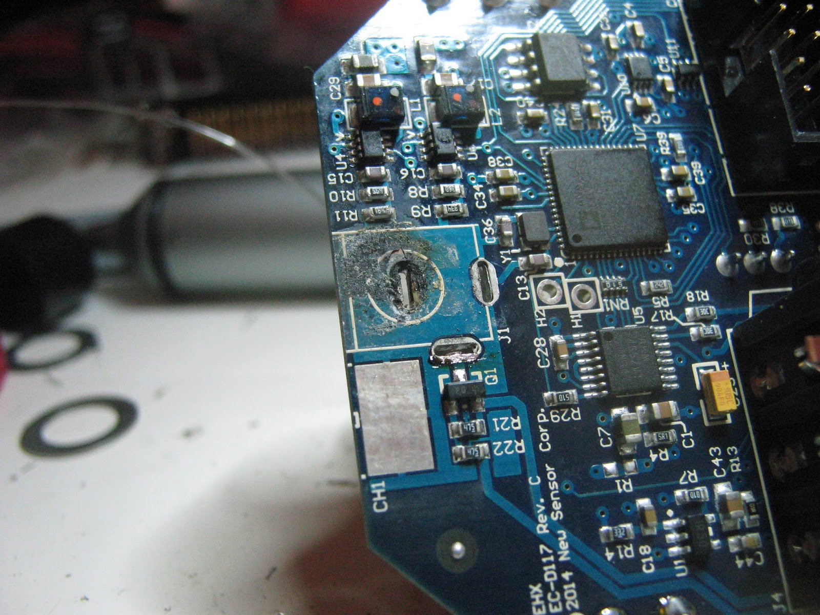
When I had this working the "Octave Up" pot felt a bit weird. The shaft had actually broken away form the pot and had been re-inserted. I replaced it with a new 5Kohm part from Smallbear which is an almost perfect match.

 
That's it. Maybe someday I'll look at the HOG series as well.

Sunday, 18 February 2018

Electro-Harmonix Pitchfork

I don't know if the PitchFork exists alongside the POG series for market segmentation reasons or as a direct competitor to the Whammy pedal. Whatever the reason, EHX have another polyphonic pitch-shifter/harmonizer with a slightly different feature set, and strangely, a lower price. This one will add a harmonized voice at a selectable interval, at a higher or lower pitch or both. You also get a clean blend. There is an expression pedal control and the footswitch can be set to work in a momentary mode, which suggests Whammy style punch-ins, but it does POG style octaves as well.


The insides are very similar to the newer POG pedals, with an Analog Device Blackfin DSP (ADSP-BF592) and a AKM AK4552 24-bit/92 kHz ADC/DAC. There is also a 25L1005 serial flash with the program code - I did end up desoldering and dumping this in case I come across another and need it.

Picture taken after repair - clean.


Taken before repair - PCB appears cloudy

This one would not show any signs of life, and turned out to be shorting out my power supply. The reverse polarity diode (D2) on the back of the DC jack measured as a short circuit, so I removed it and the pedal worked! For about 10 or 15 minutes. Something else between 9V and ground was shorting.

11-detent "Mode" pot showing some stains
After a little while spent probing around and occasionally getting a short burst of life followed by nothing, I noticed that one pot had some corrosion on the back sides. I desoldered it and wire-brushed it until it was clean but couldn't figure out how this would be the cause of the problem. The corrosion was probably from some liquid spilled into the pedal.

I could see some kind of dirt at the power jack, so I removed it and things were then pretty obvious, some liquid had been trapped between the jack and PCB and had corroded the board, causing intermittent shorts.

Original DC jack

..and underneath the jack
Some scrubbing with PCB cleaner and a new DC jack later and it is rock-solid. The rest of the board was cleaned as well, what looked like cloudy flux residue was probably stains from dried liquid.

This is a pretty clear case, something was spilled and the pedal was never taken apart and cleaned afterwards. If it had been looked after at the time then no parts would have needed replacement. Underneath DC jacks and instrument jacks are probably the worse places for this, as they can trap liquid easily.

Monday, 14 August 2017

Electro-Harmonix Pog (Big Box)

binary is hereFollowing the Nano POG & POG2, here is the original big box Electro-Harmonix POG. The big POG has mostly the same set of features as the POG2 - it doesn't have presets and the filter has fewer settings, but there are separate detune sliders for the 1 & 2 octave up harmonies.

No slide pots were placed this time
In keeping with a trend I've noticed with EHX products, it's completely different on the inside than the other POG pedals. The POG2 and Nano POG use Analog Devices BlackFin DSPs, the OG POG is much more late 90s and has a DSP56364 and a 8051-style P87C52 MCU, just like some Line 6 products, or the Digitech Whammy. I have no idea why this cheap microcontroller family is so commonly found alongside the DSP56K series but I'm starting to suspect there is an application note somewhere that shows how to use these parts together. The AK4552 codec and 2272 & 5532 opamps are also very familiar by now. A TLV1543 ADC reads out the slider positions.


DSP56364

This pedal is also an outlier in that the complete factory schematic is online at Freestompboxes. The P87* series MCUs are OTP (but could be replaced with a compatible programmable part), so I have dumped this one. There is no other programmable part on the board so this should hold firmware for both the MCU and the DSP. The binary is here.
There are a lot of unpopulated parts in the PCB layout, some may be used for development and some look abandoned. There are footprints with silkscreen labels that indicate that they are for MIDI control and the schematic also indicates MIDI was planned at some point. I didn't experiment.

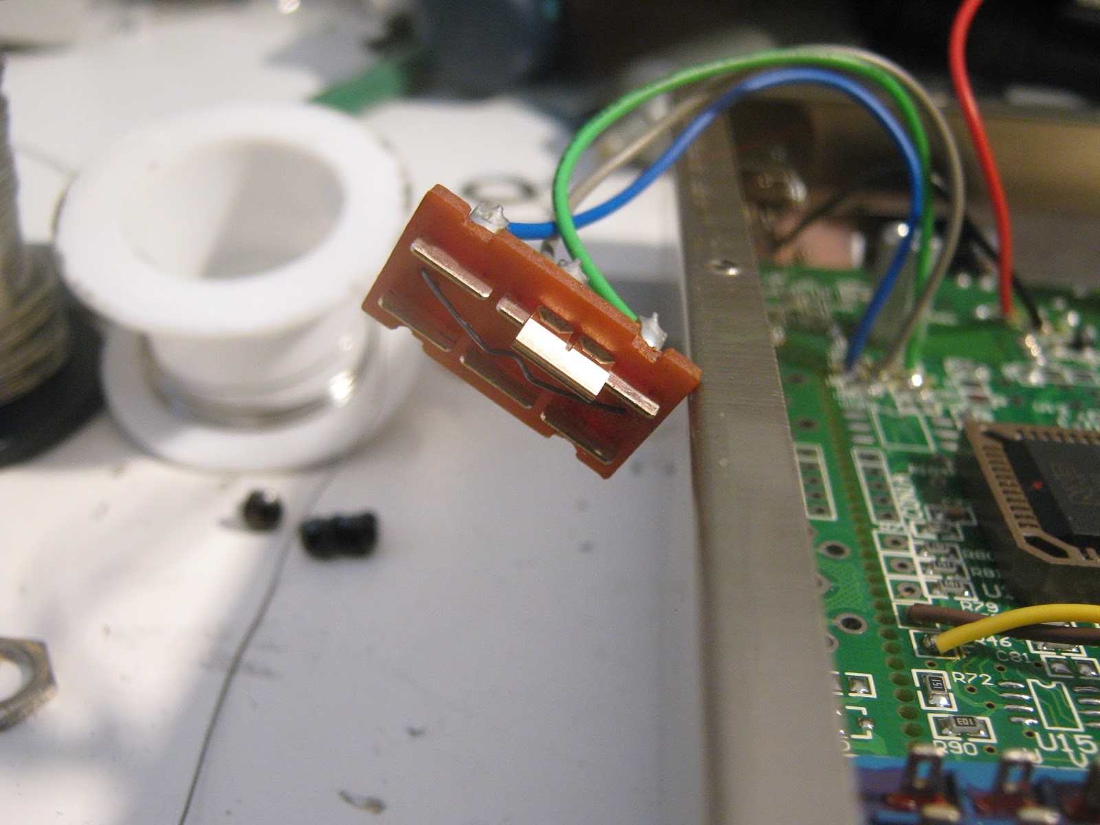
Trashed slide switch

No complicated fix for this one, once I had rigged up an 18V supply I found that the LPF mode switch was broken and a couple of wires looked like they were about to come off the board. After some solder touch ups everything worked fine. It sounds very much like the POG2, but as I don't own one anymore I couldn't do a direct comparison.

Monday, 15 May 2017

Electro-Harmonix Pog2

Much like the Nano Pog repair, this one is also written up after the fact and I have probably forgotten a lot of important details. I sold this one on, so this is mostly based on blurry pictures I took.

I got this with one of the slide pots broken off, and dead on powering up. The picture below is out of order and was taken after it was repaired.


All good.

Inside, the problem was immediately obvious. FB3 near the DC jack is missing but the pads have visible solder on them. It's very common for high-speed digital pedals to have ferrite beads installed on the 9V input and ground lines, to keep high-frequency noise out of the power wiring and comply with EMI/EMC regulations.

Guts
FB3 is gone.
My guess is that someone broke off one of the slider pots and tried to remove the board for a repair. It looks like an attempt was made to desolder the 9V jack and FB3 was lost in the process. I added an 0805 ferrite bead and the Pog powered up again, everything working.


 The architecture seems to be similar to the Nano Pog, with a larger Analog Devices ADSP-BF531 DSP, and additional controls for filters, volume swells and presets.

After desoldering the broken pot.


Replacement slider pots are available from Small Bear, replacements should be 10 kOhm. They also sell the rubber slider tips.

Update: I came across a similar repair at this blog that states the pots are 5k. My order confirmation email says 10k, I'm certain I matched the new part to the old one. It's likely that these are just used as voltage dividers and both values may be used in different batches or versions.

Compared to the Nano, I much prefer this version. The additional octaves are nice but attack/filter controls really take this from being a novelty to something pretty inspiring. Fun!

Saturday, 6 August 2016

Digitech Whammy 4

I have a bit of a backlog of stuff I've done but not found the time to describe here. It's probably best to do so before I forget everything.

Big red pitch shifter. Another 90s digital classic. I used to own one of these these but moved it along because I didn't really get on well with no polyphony and the artifacting didn't always sound too great. I think these older Whammy pedals are pieces that need to have music written with them in mind instead of just switching them on and playing the usual stuff.


A pedal large enough that the photos look terrible

Sold as not working and had had a true bypass mod done. I was hoping that it just needed calibration or that there was a simple issue with the true bypass work. Instead it just flashed all the LEDs once when powered up and then did nothing.

Inside we have a large PCB that fills most of the enclosure. There's another Motorola 56k DSP56362 (same as some of the Line 6 and EX stuff), an Atmel 89C55 (8051 architecture), a Cirrus CS4224 Codec, the MIDI optoisolator and some CMOS logic chips and opamps. The DSP56k/8051/CS4224 seems to be a really common choice of components for late 90s/2000s digital, it's very similar to what was in the Line 6 pedals I looked at previously.

The mod work was pretty bad, the wiring used was way too thick and was under strain, there were ferrite beads cracked off the PCB and the 3PDT footswitch fell apart when I was removing the old wiring.

Main PCB and LED/encoder PCB

Atmel 8051 MCU under the sticker

This has the annoying 80s/90s practice of including an AC power supply to create positive and negative voltage supplies instead of using switching converters and running off 9V DC. There are 3 linear supplies, +5V and -5V for the analog stuff and 3.3V for digital. The 3.3V was down near 0V and the regulator looked scorched, so the heatsink was desoldered and I replaced it. No change, so there is excessive current being pulled somewhere. 3.3v to GND measured around 40 ohms. I removed any 3.3V bypass capacitors in case they were shorted, and then noticed that the main DSP chip was running pretty hot.

At this point I gave up for a little while. The DSP is a 144 pin QFP and in it can be difficult to find reliable suppliers of these 56k series parts these days. There are also no schematics for this pedal online, so I would have to trace things out or make guesses.

I tried contacting Digitech and asking about a schematic, and they replied with a PDF within an hour! Here it is https://drive.google.com/file/d/0ByVCt2OFhXnyZS1JZFlmb0Z3VTA/view?usp=sharing&resourcekey=0-vBilBFlfU0YChMUrFsavrg

I also found that this IC is actually still stocked at a lot of distributors, just not in huge numbers. I decided to get one from Farnell for around 18 euros, Digikey have them as well.

Removed the original bad DSP was difficult, as the chip is quite big and there is a large top-side ground place surrounding it that takes a lot of energy to heat up. After not much progress with hot air I flooded all the pins with some Chip-Quik low-temperature solder that I had. This kept everything melted and worked well but made a mess, there were blobs of solder all over that region of the board that had be wicked and scraped off. I realised afterwards that I should have tried using a larger air nozzle for a chip this big.

After DSP removal, there is solder everywhere
After wicking and cleaning the board

 The new chip went on easily enough with some tacky flux. The true bypass mod removes the original momentary footswitch, but this switch is still needed to calibrate the footpedal, so it is usually replaced with a pushbutton mounted to the back of the enclosure. In this case, the switch was connected to the board using the original connector and then fixed down with a big blob of hot glue (you can see this in one of the pictures above). Unfortunately, all the rework heated the board enough that this glue melted and ran all over the board, leaving a thin layer around the MCU. Now nothing happened when powering it. I could peel off  some of the larger pieces of glue but most of it needed to be scraped. At this point I gave up temporarily again.

DSP resoldered,Glue cleaned, C52 replaced, Y1 removed, cleaned and repopulated
I came back a couple of weeks later and used some IPA and cotton swabs to get off the rest of the hot glue. C52, Y1 (crystal oscillator), the momentary switch connector and some of the legs of the MCU were the worst effected, so I removed all of those except the MCU and cleaned the board as best as I could. Y1 was pretty badly coated in glue, so I cleaned it and repopulated. I tried poking around wit an oscilloscope probe and found that every time I touched one of the pads of C52 the LEDs would flash. The schematic says that this is the reset timing cap, so presumably the MCU was never being reset. I replaced it with a 1uF film cap I had on hand and the Whammy fired up. I can only guess that swapping the DSP was successful, but that the hot glue was preventing Y1 from oscillating and the MCU from getting a clock signal, or C52 was bad, or both. After redoing the true bypass wiring everything works.

There is also a 1k serial EEPROM on board, but it is connected to the DSP and not the MCU, so I think it for saving calibration settings and not the program code. I would like to dump the MCU if possible, but I'm going to leave this alone. If I come across a scrap board I'll pull the chip and try to dump it. There is also a JTAG debug port wired to the DSP, I haven't looked at that at all.

Was this worth it? Replacement parts ate up a good portion of what I would have gained from selling this, and I have more than a few hours invested in it, so probably not. The newer models add polyphony and have lowered the value on these older units too. I'll add a LED (mysteriously missing? Maybe someone killed this halfway through a mod) and sell it on. I'm glad to have swapped out a QFP144 successfully and found a schematic for this, so I'm still thinking of it as a win.

Tuesday, 19 July 2016

Electro-Harmonix Nano Pog

Polyphonic pitchshifter, in a small box, put into a bigger box. I forgot I did this one. I took a look at this around November 2015 for Moose Electronics who was doing a custom re-house with mods for someone. The pedal had stopped working somewhere between coming out of the original enclosure and going into the larger one he had made for it. I found some pictures on my camera and I actually took some notes, so the details shouldn't be completely hazy.

Work in progress pedal. Wiring was temporary.

ADSP-BF592
Surprisingly, EHX seem to have several different digital designs on the go, using pretty different architectures. They even have multiple polyphonic pitchshifters on the market, with the POG series competing with their Pitchfork. I guess they may be doing some market segmentation and charging more for the established Pog brand. I have also heard that they may be using different designers for different products, which might explain why they use different processors in some products instead of a single unified architecture.

The insides are typical modern EHX, board-mounted jacks, power connector and pots, with a soft-touch momentary switch for bypass. Bypassing is done with a DG419 analog switch, which is a little unusual as they normally use a 3DPT mechanical true bypass (possibly why this was rehoused?) For anyone wanting to convert these, you can short the switch pads and the pedal will always start up in effected mode and stay there. There is a huge programming/debug connector in the top-right.

The Nano Pog has an Analog Devices Blackfin DSP (ADSP-BF592 http://www.analog.com/en/products/processors-dsp/blackfin/adsp-bf592.html#product-overview) doing nearly all of the work. This is a more modern and significantly more powerful part than I usually see, most digital pedals I've looked at recently have used the older Motorala/NXP DSP56k series. The part will run at 200 MHz but I didn't think to look at any clocks on the board (I also didn't have an oscilloscope with any hope of seeing 200MHz signals at the time). AKM AK4552 24bit/96kHz codec is handling conversions.

A TI TPS61620 (http://www.ti.com/product/TPS62120) forms a step-down regulator to get a 3.3V supply from the 9V input. TPS60403 (http://www.ti.com/product/TPS60403) is using as in inverting charge pump in a neat SOT23-5 package. Apart from some opamps (TLC2272C) and an EEPROM that's pretty much it.

This thing had a pretty awful sounding distortion that farted out badly on low notes. The effect could be heard and it tracked correctly, so the digital guts were working correctly. I usually check all for power voltages first, wherever is immediately convenient. The DSP was getting 3.3V. I know what to expect with the opamps, looking there found 9V at V+ and something like 0.5V at V-. Poking about the board found that the charge pump had the same mystery voltage on it's output. The ceramic output cap (C39) is right at the edge of the board and looked like it had been cracked, maybe from taking it out of a tight-fitting enclosure. Not the best layout decision but it probably doesn't matter as most people won't be taking these apart. The datasheet (http://www.ti.com/lit/gpn/tps60403) recommends a 1uF output capacitor, and I had a sample kit of 0805 ceramics, so I tried replacing it. I now had -3.3V at the opamp negative supply pins. I don't usually see +9V and -3.3V supplies like this in pedals. Opamps will work fine with asymmetrical supplies, their outputs will just be limited by them in the usual ways. Pitchshifting should have unity gain, so there's no need for huge output drive. Low voltage charge pumps are easier to find these days too, most won't handle a 9V input. I just don't know why this was chosen over the usual virtual ground/split supply system, as that would allow similar headroom and would eliminate an IC.

Anyway, this was a quick enough fix and it sounded clean afterwards. The polyphonic tracking is cool and it doesn't have much of the shrill digital artifacts you can hear on the octave-up settings on some pitchshifters. I only played with this briefly before handing it back, and although I liked it it didn't exactly inspire many applications. I might need more time with these.


Finished rehouse.

The final version came out great, I think additional A/B outputs and some momentary switching were the custom options.  https://www.facebook.com/mooseelectronicsdublin/