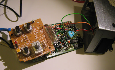
Inside, there is a two PCB construction with a hard-wired ribbon cable. The top board has unpopulated parts, I would guess that a DML10 (modulated delay) could be built on this same board by populating an opamp LFO and adding the two extra pots.
 |
| DDL10 internals |
The bottom PCB has two 4164 DRAMs, an NE571 compoundor, LM311 comparator (most likely used as part of an ADC as in the DD-2 and PDS delays) and a bunch of opamps. The SIL (single in-line) package chips are M5218L low-noise preamplifiers, used in lots of Japanese pedals. There are only 2 4164 64kb DRAMs, the DD-2 has 3. Either the DD-3 has higher sampling rates, or the Ibanez uses 8-bit samples instead of 12-bit. This is still more than the single 64k seen in Digitech PDS 1 second delays.
 |
| Main PCB, component side |
The back side of the lower board just has a main controller MC4101F IC. I can't find any info on this, it's almost certainly a custom controller for digital delays (like the Boss/Roland RDD63H101).
 |
| Main PCB, back-side. |
This unit looked mostly dead, it passed no effected signal and LED didn't respond to the footswitch. I thought the back of the larger board looked a bit crusty so I clean it with 99% IPA, afterwards I saw the LED blink with the footswitch. Still no signal.
I couldn't find any schematics for this model online, but someone has scanned and uploaded an Ibanez factory schematic for the DFL10 flanger from the same series, which uses the same controller IC. There is a full pinout.
 |
| DFL10 schematic page 1. |
 |
| DFL10 schematic page 2. |
From the schematic, the clock signal for the controller looked like it was coming from a VCO to pin 26 ("2F"). I probed my board and found that I did have a clock signal, it could be varied by turning the Delay knob, and I also had what looked like communication between the controller and the RAM chips.
At this point I got really lucky. There was a 100uF electrolytic capacitor near the LM311 comparator that was a little discoloured. While taking measurements I noticed it was getting warm. I pulled it from the circuit, and the pedal started passing a delayed signal. This cap is connected from 5V to ground right next to the comparator input, if the cap was leaky then it would effectively mute the comparator. Everything worked without this capacitor, I replaced it anyway with a new low profile 100uF for peace of mind.
 |
| Faulty capacitor pulled. |

Really smart to think of going after that DFL10 schematic! Thanks for posting.
ReplyDeleteThis comment has been removed by the author.
ReplyDeleteHas anyone been able to find out which is the best product among those listed here?https://latestmusicalinstrument.com/best-computer-for-music-production/
ReplyDelete