Showing posts with label distortion. Show all posts

Tuesday, 14 July 2020

DOD American Metal

Another quick one. This American Metal would power up, pass a clean signal but wouldn't pass an effected signal.


Schematics are older DOD pedals aren't too hard to come by (I believe some of them were supplied in the original boxes). I suspected a bad switching JFET was blocking signal, but they all measured fine on the oscilloscope.


I found that two of the transistors near the distortion control had very little voltage on the collectors. The schematic shows a series 1k resistor and a 47uF capacitor from the 9V supply, so there's a good chance that capacitor is shorted.


The 47uF is right in the middle of the PCB. Pulling out brought back the effected signal, so I replaced it and put things back together.

This is a very cool pedal, definitely in the HM-2 family. Maybe not as much gain and not as much EQ control, but it certainly does the buzzsaw sound when turned up.

Thursday, 1 March 2018

TC Electronics Nova Drive NDR-1

Programmable overdrive & distortion from TC Electronics. All overdrive/distortion parameters are controlled digitally, so presets can be saved and recalled, the order of the two circuits can be changed, they can be run in series or in parallel. All of this can be triggered by MIDI.


 TC did a Nova series of pedals and multi-effects units, but I don't think they were all built around a common digital design (like the Line 6 4x4 series). TC stuff is interesting as they have a history of high quality and targeting high-end markets and they tend to use fairly modern designs and parts. Unfortunately they don't seem to release much information or contract out any repair services, so I have not come across any modern TC Electronics schematics, either official or leaked.
TC were sold to Behringer in 2015 and their latest range of pedals look to be more standard stuff, a bit watered-down compared to the Nova series. I'll reserve judgement until I see one.
This series used a 12V power supply for some reason (why not 9V, like everything else?)
This Nova Drive started up but only passed a signal in bypass mode. The LED display and indicators did react to the knobs and to button presses, which at least meant that the digital section is working and the problem was likely in the analog end.

Top PCB (digital)
The build quality is really nice, they use a folded and tapped sheet metal chassis instead of cast box. There are two PCBs inside, the first is a "mezzanine" board with the encoders, buttons and displays. There is an Atmel ATmega168 and some '595 and '165 shift registers for digital IO. I'm pretty sure the ATmega is reading out pots and buttons and controlling something on another PCB to vary the effect parameters, as well as driving the LED displays and responding to MIDI commands. I would guess that this top PCB is probably very similar across all the Nova pedals. I am assuming the ATmega has some code-protection so I haven't tried desoldering and dumping it.

Lower PCB (analog)

The bottom PCB fills the whole enclosure - it has a bunch of opamps (presumably the analog overdrive and distortion circuits), DG441D quad analog switch ICs, switching power supplies, the MIDI optoisolator, a relay and a Cirrus CS3308. The CS3308 is a cool part, it's an 8-channel digitally programmable volume control. Presumably each channel is mapped to one encoder (4 knobs for overdrive and 4 for distortion) and the ATmega sets the levels over SPI or I2C. TC have used the +-5V version with 123 dB of dynamic range, which is kind of ludicrous for a distortion pedal.

Lower PCB, backside

U3 generates -12V from 12V input

All parts on this side are glued in placed before soldering

The bottom PCB is very parts-dense, but helpfully there are test points for all supply voltages. I found that -12V was reading very low and so all of the negative supplies that are derived from -12V were also missing. -12V appeared to come from a switching supply controlled by a CS51411 on the underside of the PCB, the circuit looks liked a close match to the inverting converter in the datasheet (Fig 25). The inductor was getting burning hot, so the switching IC was a pretty likely culprit. TC used a double sided load for this PCB, and parts on the underside are wave-soldered instead of reflowed, which means they are all held in place with a dot of red epoxy. Desoldering the IC took a lot more heat and force than I'm used to but it did eventually lift off. It still didn't work with a new chip, solid 12V DC across the inductor with no switching happening, which explains the heating. The SYNC pin did have a ~340 kHz square wave - I don't know if this was also present on the original chip. The huge number of test points on the back of this larger PCB suggests TC use some kind of bed-of-nails jig for testing during manufacturing.

Around this time I held my hand over the board when powered up and found another hot spot. One of the two DG441D switch ICs was also running hot, so I desoldered it. This part does run off +12V and -12V rails, so it may have killed the -12V supply when it failed.

There is another switching power supply using a L5970D controller - this one is generating 3.3V for the digital parts and was working correctly.

As I knew there may have been a short from -12V to ground or some other supply, I wanted to see if I could completely isolate the CS51411 from the -12V supply and use an external power supply to provide -12V. I removed the output capacitor and the inductor. Using an bench supply wired to the board and providing -12V, the pedal worked. Surprisingly, it pulled over 100 mA which seemed very high for some opamps and switch ICs so there may have been some other damaged part on that -12V rail.

The series/parallel switching did not work, only series mode passed a wet signal. This confirms the DG441Ds are routing the signals into series or parallel combinations, one of them was still missing. A new IC here restored all modes.

The CS51411's inductor measured 33uH out of circuit which seemed correct. I decided to try swapping it with this part, which fixed all the power supply issues. I am guessing that the old inductor got so hot that it reached it's curie temperature and it's magnetic properties changed (??) The new part runs cool. Looking again at the CS3308 datasheet shows it pulls 36 - 50 mA on both positive and negative analog supplies (!), which explains the high power consumption seen earlier, and why the pedal originally shipped with a 12V supply rated for 400 mA. This chip does run noticeably warm, but the power consumption matches the datasheet figures. I can only guess that power consumption is targeted  high to help lower noise and increase dynamic range. For a distortion pedal a low-power version with poorer specs would probably be a much better fit. The pedal will actually work with 9V input, and will generate a -9V supply instead, but will need a beefier supply than is usually seen on pedalboards.

All good again.
I broke the ribbon cable connecting the two boards when I was working on this. I just replaced it with individual wires - I would really like a tool that strips ribbon cable so I could just buy a small reel, if anyone knows of one please let me know.

Wednesday, 31 January 2018

Tech 21 XXL

I picked up this 90s Tech 21 XXL as I had read that it was a "sleeper", a nice distortion but not particularly well known. I knew that the design was based on opamp clipping with no diode clipping. I have never built or (to my knowledge) even played anything like that, so I was curious and also pretty confident that this would be simple to repair. This one would power up and would pass a bypass signal but the effected signal was very quiet - volume and gain had to be cranked all the way to hear anything. The tone knob sounded like it was working correctly. A bad opamp or switching FET maybe.


The insides were a bit of a surprise. All the jacks and pots are board-mounted, but it looks like it was assembled using the least amount of solder possible. A lot of the through holes are not completely filled. Re-soldering all these joints didn't help.

Dull joints, very little solder

This construction style is very annoying to work with. The input/output jacks do not butt up flush against the sides of the enclosure like with many other common designs, instead they extend through the sides. This means that the whole pedal has to be basically assembled inside the enclosure, the jacks and pots are installed and the PCB is aligned with all of their pins and then soldered in place. This seems very labour-intensive and makes any kind of repair a real pain.

WTF

After desoldering the 1/4" jacks and DC power connector I managed to get the PCB out and found another surprise on the other side. Tech 21 have used a SMD design (fine) but have covered it with a block of potting compound, presumably to prevent clones of the distortion circuit. Unfortunately this makes repair much more difficult as well.

The switching FETs actually seemed to be working correctly, so I decided to see if I could remove the potting (there are methods for this written up online, often described as "de-gooping"). I guessed that potting material for surface mount parts are probably softer than old-fashioned epoxies to prevent them from cracking solder joints as the compound cures. I hoped that heating with hot air and picking with a tweezers might be hood enough.

Potting removed, plus some parts

De-gooping went fairly well, I started at 100C and the compound cracked and separated from the board in large pieces. I increased the temperature as I went but eventually went too far (I think above 250C) and re-flowed some solder joints - this meant an entire chunk pulled away from the board, holding two opamps and some passives with it. The resistors and caps were easy enough to separate and re-populate, the opamps were replaced with new parts based on a schematic I found.

Restored jumper. Cut trace is visible.

Another surprise, my pedal is a different revision from the one photographed on Diystompboxes. It has a cut trace and a jumper wire embedded inside the epoxy block. Is this a genuine correction, or something designed to make reverse-engineering more difficult?

The pedal still didn't work with new opamps, but now that I could probe them I could see one was not getting any bias voltage on one of the inputs. The Warp control which sets the DC bias of the first opamp was not connected to +9V, I found a trace to the pot that was open circuit, possible from a scratch from a nearby electrolytic cap. A jumper wire fixed this.

Restoring +9V to Warp pot.

Re-assembling was another pain in the ass, I broke the DC jack and had to order a replacement with PCB pins instead of solder lugs. Getting the board into the enclosure and aligned with the jacks so they can be soldered is fiddly, in retrospect I should have tried to replace the jacks with the more common units that have a parts that threads from the outside of the enclosure, like modern EHX stuff.

The XXL sounds quite good - less compressed (and less sustain) than what I would usually expect from a diode-clipping distortion like a RAT. The Warp control doesn't seem to do much throughout a lot of it's range. It also does very little with a weak input signal (especially single coil pickups), probably because the first opamp stage isn't driven into clipping. With a loud signal generator I could different hear distortion flavours, presumably the clipping gets more or less symmetrical through the pot travel. Online reviews and clips confirm this, so I'm confident this is working as expected.

I like this pedal, but I'm a bit soured by the weird construction and the complete lack of giving-a-shit towards repairs. Uncovering the circuit took less than an hour, so it's not much of a deterrent to anyone who wants to make a clone, but it's definitely a hurdle for finding what has wrong. I'm not sure if I think it's worth looking at more Tech 21 stuff.

Saturday, 11 March 2017

T Rex Mudhoney II


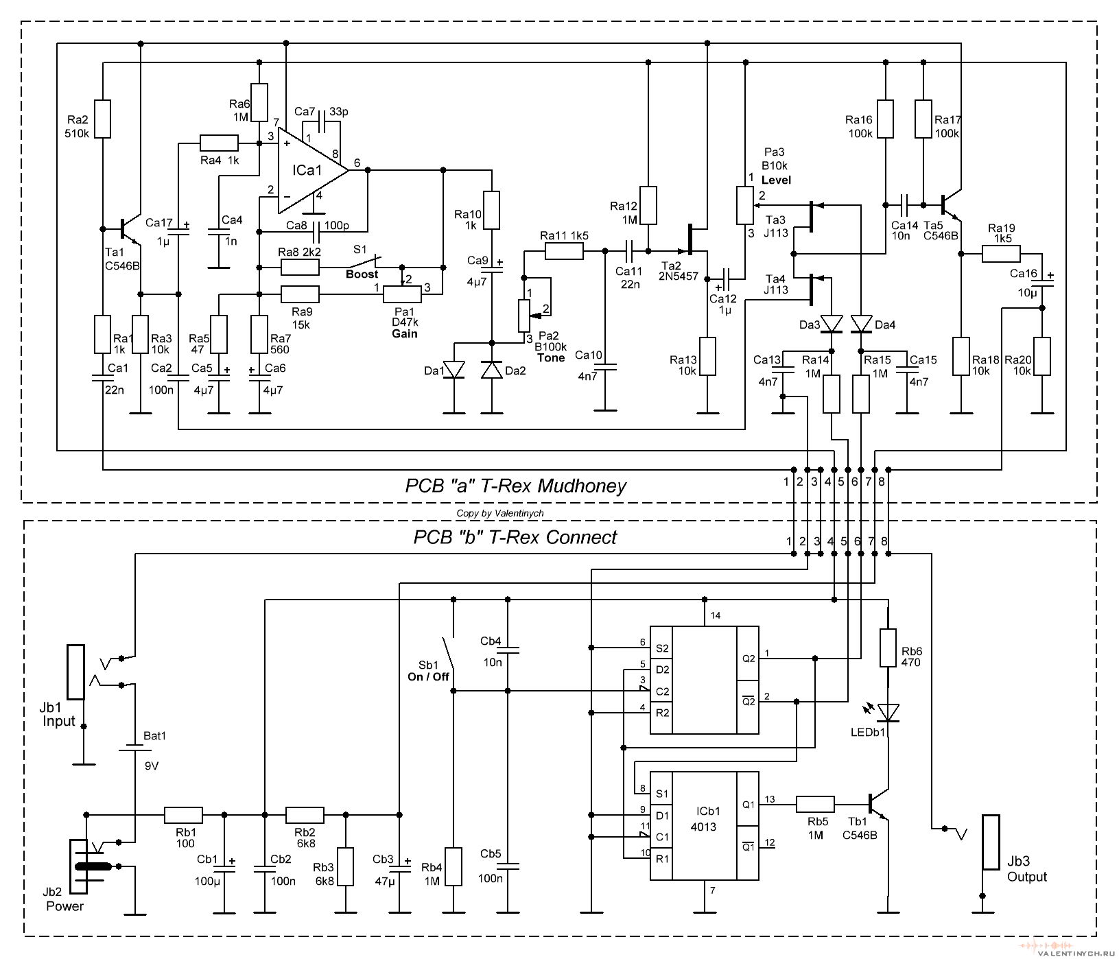
This is something like two slightly different Proco RAT circuits in one box. As received it only seemed to work with very heavily attenuated output volume. Maybe it was something to do with an electronic switching system.

Shown here without footswitches


The PCB photo came out very noisy, but the inside is just a CD4013 dual flip flop IC and 2 OP7 opamps driving some diodes to ground - I believe this is standard for modern reissue RATs. The red wire and replacement capacitor was a previous repair. The switches are held by rectangular cut-outs in the PCB, I like this method.


As well as being very quiet, the LEDs underneath the tone pots were not lighting up. I guessed that the 4013 was driving some switching FETs and it was dead.


First attempt at a fix was replacing the CD4013, as these are cheap and I can replace SOIC parts pretty quickly nowadays. No change. Probing the new chip I saw it was getting no power - I should have checked this first. I followed the traces from the 9V input outwards and they were hidden underneath the input jack. That had to be removed.

Input jack removed
Underneath was a trace carrying 9V that ran right next to the edge of the board and had been cut right through. I added a wire from to restore 9V to a power bypass cap at the 4013 and reinstalled the jack. Now the pedal lit up when engaged, and the left side (channel 1) was loud and sounded pretty great. The right side still had a very low output volume, much less than unity.

I hooked up a signal gen and tried to follow with an oscilloscope to see where signal was lost. Thi schematic was helpful. The opamp has outputting a 6Vpp signal but this was lost at the tone control, so the problem was probably somewhere in between. Testing the clipping diodes showed that one was shorted. I guessed and lifted one off.

One clipping diode removed.

This was lucky, that diode tested as a short out of circuit. This side of the pedal was now much louder, but less distorted than the other side as only half of the signal is getting clipped. These diodes are MELF packages and I can't find any identifying markings on them. The remaining diode measured around 0.5-0.6V on a DMM, so probably something silicon. Internet consensus seems to indicate that these pedals used 1n4148, and I had MELF 4148s at hand, so I used that.


My hand soldered replacement looks different to the reflowed diode. The good news is that it sounds the same as the other channel, and now both will get fairly loud. I forgot how nice a RAT can sound.