Sunday, 5 March 2017

Dunlop Cry Baby 105Q Bass Wah

Unlike the traditional Crybaby, the Dunlop bass wah doesn't use a stompswitch to switch the effect. Instead the pedal is spring-loaded to return to the heel position, where it engages a small momentary switch which bypasses the pedal. You only have to lift a foot off to disengage the pedal, which makes using it for just a few notes much easier (maybe this was thought to be more useful for bass players). The downside is that it can't do cocked-wah sounds without a foot holding it in place.

This one doesn't switch at all, the output signal is always in bypass mode. It does seem to work in that it buffers the input signal, and when power is removed no signal is passed. This is likely to be a problem with the switching system.


The insides are very different to the Crybaby. This is an inductor-less wah, with 2 quad opamps doing the filtering, presumably with a gyrator design. The normal Dunlop Hot Potz is used.

Momentary button desoldered
The switching system uses a small momentary button soldered on to the hidden side of the PCB and poking through the top of the enclosure. One side of the switch looked like it was always closed, so this was replaced with a new one - without fixing the problem. The transistor is just buffering the switching signal, with the new switch installed this could be seen changing from 0 to 9V as the pedal was lifted and dropped, so this part of the PCB is working correctly.

Main board.
All of the rest is done with 4 ICs. The MC33174 opamps are almost certainly doing the filtering, the CD4066 analog switch is routing signals when changing from bypassed to effected modes. The signal from the momentary footswitch is running into a CD4049 buffer. There are some Rs and Cs around the buffer, I would guess it is de-bouncing the switching signal to cut out any popping. There was no activity on any of the CD4049 pins.

4098 buffer desoldered.
I took a picture after I removed U3 but apparently forgot to take one after I soldered a new part. The new chip correctly sent on the switching signals and the pedal wahs once again.

This is a pretty nice design, I only tried it with a guitar as I didn't have a bass around at the time. I would have guessed that the pushbutton is the weak point, but in this case it seems an IC died first.

Saturday, 4 March 2017

Empress ParaEQ Repair

This is another case of getting to look at something  nicer than I would normally get to play with. When it comes to guitar gear I am pretty cheap, and it's hard to justify spending a lot on "simple" pedals (this is a dumb distinction to make). Empress' ParaEq seems like it's probably worth it, it's a good idea executed really well.


This is basically a 3 band EQ (low, mid & high) with adjustable centre frequencies and independent Q settings. There is an input pad and a clean boost as well. The build quality is very high - the toggle switches are positioned behind a row of knobs to protect them from stomping feet, and the pots all have nice metal knobs. Empress seem to do pedal graphics with enough personality to not be completely boring to the eye.

Revision 7, Jan 6 2014. Copyright date is 2013...

Inside we have:
- OPA4134 & 2274A quad opamps, buffering, amplifying & filtering.
- an ADG442 analogue switch for the buffered bypass
- TC7760HE charge pump controller for a negative voltage rail.
- 16F630 Pic microcontroller, monitoring footswitches to change between relay and buffered bypass.
- a SOT223 package, marked "4576". I'm certain this is an LDO and I think I had the part number and looked over a datasheet but I have lost it again.

Plugged in, the pedal was completely dead. My little test amp was humming, which usually means a power supply is shorted out somewhere and some filter caps can't do their job. Measuring inside the pedal, the DC jack read at ~2.5V (using a 200mA Boss power supply).

Flush mounted DC jack

No through-hole anchors for the jack.
Something is pulling power to ground, usually this is a bad power filtering capacitor, bad IC or a shorted protection diode. Empress are using a surface mount DC jack which must be desoldered to remove the PCB from the enclosure. I guess they really wanted the power jack to sit flush with the edge of the case. I took it off to see if there are more parts or any damage on the backside.


There is nothing on the backside. I took pictures of pots while I was here.

Gain pots are B5K.
Frequency pots are marked "B1 P1416C"


As there are not too many ICs on the board I tried to order them in likelihood of failure and then removing them to see if the short cleared. Pulling these chips off is pretty fast with hot air.
The 7660 was first, as I have seen these fail before. No change. Then I removed U1, the sot-223 LDO and the short was gone - but as this chip is powering all the opamps I couldn't say of this was the problem or not. U101, a 2274A quad opamp had a mark on the casing which may have indicated some kind of failure, so I removed it and replaced U1. Short was gone, I now measured +8V at the opamp positive rail and -6V at the negative. It passed a signal, the LEDs now lit up when the footswitches were pressed, and the boost worked. The EQ controls did nothing, so obviously this opamp was handling some of the filtering.

U1 & U25(?) removed.
U101 removed, short cleared.
After soldering in a new opamp everything worked as expected. Re-soldering the power jack is easy with some kapton tape holding it flush to outside face of the enclosure.


This is a more useful design than I had expected, parametric EQ solves a different problem than a graphic EQ. It's much easier to sweep the frequency control with a high Q and identify exactly what will be boosted or cut, it always allows adjustment of frequencies "between" the bands available on a graphic EQ.

The only downside for longevity is the PIC - again, this is a programmed part. If it was bad I would not have been able to replace it and would have had to re-wire for true bypass.

Sunday, 12 February 2017

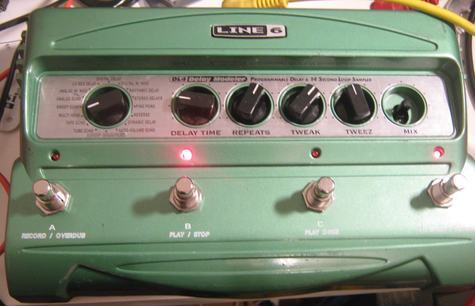
Line 6 DL4 final fix

A short update on my DL4 that had come back from the dead but wouldn't run as a DL4.

I went through 3 replacement DRAM chips and none of them worked. With all of them I got distorted noise instead of a delay signal. Yesterday I sat down with a schematic and beeped out every pin of the DRAM to the DSP. The RAS line (pin 45) of the DSP wasn't quite soldered down, so the RAS pin at the memory was open. Some flux and a quick touch of the soldering iron and now it works with external memory and runs the DL4 firmware correctly.


New RAM chip. The flux mess was cleaned off afterwards.

The DRAM that I know worked was a Toshiba TC51V17805CFTS-60. I think any 16 Mbit DRAM with the same standard pinout will probably work here.


Sunday, 29 January 2017

Electro-Harmonix Deluxe Memory Boy

Another quick one. This is the high-end version of the Memory Boy that I've looked at before. The Deluxe adds an extra gain control, tap tempo, tap divide, a rate control for modulation, an effects loop and the ability to control rate, depth, feedback or delay time with an expression pedal.
I got this used with a fault, the seller said the delay signal was very quiet compared to the dry. I plugged it in, and sure enough the delay was kind of weak. The manual for this one says that the added Gain control goes from -6 dB to +20 dB. When I put it straight up at 12 o'clock the delay seems to match the dry signal in terms of volume. I can't find anything wrong with it so I'm just taking a look inside.


Both PCBs.

The guts are similar to the Memory Boy, 4558/LM324/TL072 opamps, SA571 opamps and of course the 4 BL3208A BBDs. There is an ATMega16 microcontroller doing the tap-tempo and probably modulation waveforms as well. There is a JTAG port but I don't know how to dump the ATMega through JTAG, and I'm fairly certain it will be read-protected anyway.

BBD board, front
BBD board, backside

The BBDs are on a daughterboard, as per the Boy. This time they are connected with header pins and sockets and held down with screws into brass inserts instead of soldered to the main board. On the backside is the same 4011 IC used as an oscillator for the BBD clocks.


Main board uncovered

Underneath the BBD board we can see an LM13700, most likely modulating the clock frequency in the same way that the Memory Boy worked. I was a little surprised as I thought the ATMega would generate all the clock signals, it must just generate control voltages to the LM13700 to adjust the clock rate.

One nice feature is that the full IC part numbers are on the silkscreen, which should make life easier for anyone attempting to repair one.

The tap-tempo features are nice, but the rest of the pedal is essentially the same core delay as the Memory Boy. The tap-tempo does seem to allow longer delay times than the knob, around 1 second (by ear).

I'm not the biggest fan of this series, I prefer the Ibanez ES-2 for analog delays. This version is definitely an upgrade over the original if you can afford the real estate.

Sunday, 22 January 2017

Line 6 DL4 rebuild

This is the first DL4 I ever got, bought broken almost 5 years ago. Despite working on DL4s for other people and my own MM4 repair I have never been able to fix this one. It has always been something I had lying around and would take out for an hour here and there whenever I had an idea.

Board as I had been storing it. The taped on diode was a part I had replaced.

In retrospect this was a bad example to try to start with. Most of these 4x4 pedals have power supply issues or have a bad IC somewhere and can be debugged without too much hassle. With this one, I replaced the some parts in the power supply back in 2012 and got the right voltages, but it would never start up. Very occasionally the LEDs would flash on and then it would freeze or die again. Looking at the test points didn't help, it would show a master clock but no other clock signals. The MCU would usually reset correctly on power up, but would then assert the reset line of the DSP and never release it. The only good model for what was going on was that multiple ICs had some kind of damage, maybe from a severe power supply failure.

Somewhere in halfway through the process of replacing all ICs.
I had tried swapping some parts with the spares PCB I had (which is now almost completely depopulated) without any luck. I'm not clear on the exact timeline of work as things were quite spread out, but I know that after replacing an MCU on one of the other DL4s I bought a box of new ICs and replaced the one on this pedal, which didn't help. At some point I decided to order all new ICs, and I replaced everything except the DSP (DSPB56364AF100) and the Cirrus audio codec (both end-of-life and hard to find new) - no change. After swapping a DSP56k part in the Whammy pedal I built up some confidence and decided to see if I could get a replacement part for the DL4.

DSP56364

I got one from a Chinese vendor on eBay, knowing that it could be a fake part. It turned up a month or so later and I put it aside. I dug out this pedal recently and tried swapping it out. The old part came off easily but I had some trouble aligning the replacement QFP, in the end I just cheated by drowning the pins in tacky flux and reflowing the board with hot air and it soldered perfectly.

It was still dead, and now the 3.3V supply was being pulled low. It looked like I had a solder bridge somewhere on the DSP, or it was a remarked/fake/dead part with a short from 3.3V to ground. My method for finding shorts to ground on a board has always been to guess where the short might be and remove parts until it's gone. I had read about a technique for finding shorts where a constant current is fed into the power rails and a DMM on millivolt range is used to measure the voltage drop across parts that connect to power and ground. The part with the lowest voltage drop is the short - this is basically a way to make low resistance measurements with a higher sensitivity than most ohmmeters can manage. I fed in 400mA to the 3.3V rail and measured all the 3.3V coupling caps. Voltage drop was lowest near the DSP (shit) but of the 4 power decoupling caps around the DSP, C39 had the lowest drop. I removed C39 and the pedal powered up, current consumption was back to normal. I don't know if C39 was bad (it didn't measure as a short outside of the circuit) or if it had a small solder bridge I couldn't see, but I was pretty pleased with this and will use this method in future.
Coolaudio parts: V1000 & V4220M. Later removed the adapter boards.

At this point the 4 LEDs would just flash on and off, but this isn't too surprising as I had removed the audio codec and the DRAM chips. I used the modulation EEPROM that came with my MM4, as I knew that program doesn't need DRAM. The Cirrus CS4223 codec is harder to source, but I happened to have some Coolaudio V4220M chips that I bought to try with their V1000 reverb chip. This looks like a second source/clone of the Cirrus chip, so I installed one. This gave me a working pedal! I tried the DL4 EEPROM that came with this pedal and it was completely dead. I moved it to my MM4 (which has been converted to a DL4) and it didn't work there either. I reinstalled the original DRAM IC and tried the MM4's known-good delay EEPROM and only got heavily distorted noise. This seems to confirm that all of the ICs that came with this DL4 are damaged.

I now have an MM4 that acts as a DL4, and a DL4 that only works as an MM4. With Behringer/Coolaudio parts in it.

I have ordered some DRAM chips that I think will work, so hopefully this can also be used as a DL4 again.

Alive.

The parts were not too expensive (€20-30) but I sunk a lot of time into this. It's satisfying as a personal victory after having this thing around for so long but if I got one in this state as a repair job I would probably turn it down.

Lessons learned:
- a complete digital rebuild is totally possible
- it's probably not worth the cost of parts and time
- all program information is stored in the EEPROM, no ICs need to be programmed or configured
- DSPB56364AF100 are available from eBay seller "e-best_trade". Unfortunately, none are listed right now
- Coolaudio V4220M works as a replacement for Cirrus CS4223
- short finding with a constant current source and sensitive voltmeter can work really well


Saturday, 31 December 2016

Electro-Harmonix Doctor Q

I have realised that since I started this blog I have managed to post every month, except for December. I want to keep going at this, so here's a quick cheater before the finish line.

I got this vintage EHX Doctor Q for fairly cheap, missing a battery door and "not working". The seller described some torn wiring inside. I thought this would be simple.


Graphics are actually quite clean for a pedal of this age.


I tried it out with a 1/8" power adapter in the DC jack and it worked just fine. It sounds pretty good too, and worked with weak single coils and humbuckers without having a sensitivity control. Range controls the width of the filer sweep, it has a fairly sensible & usable amount of variation.

Single sided PCB.

Opening it up, and the battery snap has broken off the power jack. Quick soldering job to restore it, and it works with a battery as well. It looks like EHX were not using the extra contact on the jack to switch the battery. The pot code is a CTS with a 1978 year of manufacture, so the pedal is probably that old as well.

Unfortunately it's hard to get the board out to take pictures as I don't have tools that can easily remove the round knurled nuts that EHX were using in this period. In the interest of not scratching things up I've left them along. The circuit is fairly simple, schematic is below.


It's pretty clear what happened to this one. With a missing battery door the 9V battery can just dangle out the hole in the chassis. The battery snap probably broke off when moving the pedal around. Sometimes I'm lucky.

I have a fairly complicated envelope filter build (maybe more on that in the future) so this one is surplus to requirements. Get in touch if you are interested in buying.

Sunday, 13 November 2016

Electro-Harmonix Graphic Equalizer

Another EHX big box pedal, a mains powered 10 band graphic eq. I'm guessing this one is a late 70s/early 80s vintage. Google finds at least two versions, this one and a more modern looking black-and-yellow version with a power switch and LED/lamp. Oddly enough, none have a knob in the lower left corner instead of a stomp switch, so this may be a less common variant or someone's science project. It doesn't work - moving the sliders just brings in some noise, the knob in the corners seems to attenuate this.


A few things are apparent once the lid is off. The "master volume" is not stock, it's someone's mod in place of a bypass switch. The jacks are probably replacements, as EHX didn't use those isolated plastic jacks. There is a third jack that has been added, probably for a remote footswitch for bypass. The PCB is also broken! It's held in place to stand-offs with screws and washers and one corner has broken off. Some of the plastic sliders of the potentiometers are sheared off, it's clear that someone stamped over the sliders hard and managed to break the PCB as well. There is a pair of washers and a screw holding the board in that corner, and it actually seems stable mechanically.


A schematic was easy enough to find, the model name is the same as on the PCB art and the circuit seems to match. It's 9 notch filters (using single opamp gyrators) in parallel with different centre frequencies plus a passive 16 kHz filter. This seems to be a common design for guitar EQ. Power supplies are approximately +-13.5V using a centre tapped transformer and zener regulators.

Schematic found online
I took the board out of the box to take a lot at the pots. Date codes are from 1979. Some black foam was attached at some point, probably to keep dirt out, and over the decades it has perished and turned to sticky fluffs of black shite that are now all over the PCB and inside the pots. I cleaned these with contact cleaner and cotton buds until the pots slid smoothly. Also washed the enclosure while I had it gutted, removed the plastic jacks, installed some new metal open-frame 1/4" jacks and pulled out the volume knob and wiring.


Some of the pots have broken sliders, so it's possible that they have broken tracks or the wipers have disconnected from the tracks. I tried to measure the resistance of the left-most pot from the backside and it didn't seem to reading correctly. All the pots extremes should be wired together in parallel, and it turned out that left hand one had no continuity to it's neighbour. I tried to desolder it to measure out of circuit, and the pad and track lifted right away. The pad on the next pot also started to lift as soon as it was heated. Usually I don't see any lifted traces or pads when desoldering. It turned out that these tracks were physically broken, when the PCB corner was broken the pots must have been pulled away from the board. The left-side sliders were completely disconnected, the ones on the far right were fine and the middle were a bit flaky. I ran a piece of bus wire across the top pads to connect them, much like how the pot cases are grounded together.

Cracked pads

Pots jumpered with bus bar

At this point I clipped a test signal to the board and fired it up. Power supplies were OK. The signal didn't get any further the first opamp stage, so after checking the feedback network looked good I replaced it with a new 4558 opamp. Everything works afterward, all bands boost and cut and none have any noise or crackling.


I added a new switch and wired for true-bypass, and then managed to confuse myself when I saw a huge 50 Hz hum on the output. I thought the power supplies had gone bad and replaced the filter caps with new Nichicons. It turned out that although the enclosure is grounded, and the PCB is bolted to the enclosure, the PCB is not grounded through these bolts. Running a wire from the input jack fixed this up. At least I know this won't need new filter caps any time soon.


The extra hole in the enclosure is a decent fit for a large LED bezel and some spare hardware, I've added this as a bypass indicator.

Repaired and cleaned up.

It sounds exactly like a 10-band EQ sounds. The +-13.5V supplies mean that this has huge headroom, and it can be used to filter high amplitude signals without distorting as soon as a 9V or 18V unit.