Showing posts with label EHX. Show all posts

Thursday, 28 March 2019

Electro-Harmonix Micro Pog

I think this is the last entry in the EHX POG series that I haven't repaired. As usual, this came from eBay and doesn't work. No signs of life.


On first inspection, it looks like the diode in the switching power supply is trying to escape the PCB. I don't think that overheating could cause this without scorching the board, someone probably attempted to desolder this. My multimeter confirmed that this diode was a short circuit, so that's probably the fault. The diode is an SS14, which is also the same part used for input polarity protection. The switching IC is a CS51413 buck regulator.


I removed the diode and still measured a short across it's pads, so the switching chip is probably bad. That came off as well.


I ordered a replacement CS51413 but actually received a CS51414, which was annoying. However, the CS51313 and CS51414 are very similar, the '313 has an external sync pin where the '514 has an external bias pin. The Micro POG doesn't actually route pins 4 & 5 anywhere, so either chip can be used. I suspect that both are the actually the same die, with different pads broken out to external pins.

After replacing the controller IC and the switching diode, I still had a short from output voltage to ground. The output capacitor (C3) is also connected across these nodes, so I removed it and then the pedal worked. C3 is filtering the output of the 3.3V switching supply and doesn't seem to be always necessary. I don't know the value of C3, but the datasheet recommends 100uF. A 100uF ceramic capacitor in this package is actually quite expensive, so I used a 47uF.


The rest of the pedal is very similar to other Electro-Harmonix XO series units. There's a PIC18F2431 microcontroller, a DSP56364AF100 DSP and a PCM3052A audio codec.


When I had this working the "Octave Up" pot felt a bit weird. The shaft had actually broken away form the pot and had been re-inserted. I replaced it with a new 5Kohm part from Smallbear which is an almost perfect match.

 
That's it. Maybe someday I'll look at the HOG series as well.

Sunday, 18 February 2018

Electro-Harmonix Pitchfork

I don't know if the PitchFork exists alongside the POG series for market segmentation reasons or as a direct competitor to the Whammy pedal. Whatever the reason, EHX have another polyphonic pitch-shifter/harmonizer with a slightly different feature set, and strangely, a lower price. This one will add a harmonized voice at a selectable interval, at a higher or lower pitch or both. You also get a clean blend. There is an expression pedal control and the footswitch can be set to work in a momentary mode, which suggests Whammy style punch-ins, but it does POG style octaves as well.


The insides are very similar to the newer POG pedals, with an Analog Device Blackfin DSP (ADSP-BF592) and a AKM AK4552 24-bit/92 kHz ADC/DAC. There is also a 25L1005 serial flash with the program code - I did end up desoldering and dumping this in case I come across another and need it.

Picture taken after repair - clean.


Taken before repair - PCB appears cloudy

This one would not show any signs of life, and turned out to be shorting out my power supply. The reverse polarity diode (D2) on the back of the DC jack measured as a short circuit, so I removed it and the pedal worked! For about 10 or 15 minutes. Something else between 9V and ground was shorting.

11-detent "Mode" pot showing some stains
After a little while spent probing around and occasionally getting a short burst of life followed by nothing, I noticed that one pot had some corrosion on the back sides. I desoldered it and wire-brushed it until it was clean but couldn't figure out how this would be the cause of the problem. The corrosion was probably from some liquid spilled into the pedal.

I could see some kind of dirt at the power jack, so I removed it and things were then pretty obvious, some liquid had been trapped between the jack and PCB and had corroded the board, causing intermittent shorts.

Original DC jack

..and underneath the jack
Some scrubbing with PCB cleaner and a new DC jack later and it is rock-solid. The rest of the board was cleaned as well, what looked like cloudy flux residue was probably stains from dried liquid.

This is a pretty clear case, something was spilled and the pedal was never taken apart and cleaned afterwards. If it had been looked after at the time then no parts would have needed replacement. Underneath DC jacks and instrument jacks are probably the worse places for this, as they can trap liquid easily.

Monday, 15 May 2017

Electro-Harmonix Pog2

Much like the Nano Pog repair, this one is also written up after the fact and I have probably forgotten a lot of important details. I sold this one on, so this is mostly based on blurry pictures I took.

I got this with one of the slide pots broken off, and dead on powering up. The picture below is out of order and was taken after it was repaired.


All good.

Inside, the problem was immediately obvious. FB3 near the DC jack is missing but the pads have visible solder on them. It's very common for high-speed digital pedals to have ferrite beads installed on the 9V input and ground lines, to keep high-frequency noise out of the power wiring and comply with EMI/EMC regulations.

Guts
FB3 is gone.
My guess is that someone broke off one of the slider pots and tried to remove the board for a repair. It looks like an attempt was made to desolder the 9V jack and FB3 was lost in the process. I added an 0805 ferrite bead and the Pog powered up again, everything working.


 The architecture seems to be similar to the Nano Pog, with a larger Analog Devices ADSP-BF531 DSP, and additional controls for filters, volume swells and presets.

After desoldering the broken pot.


Replacement slider pots are available from Small Bear, replacements should be 10 kOhm. They also sell the rubber slider tips.

Update: I came across a similar repair at this blog that states the pots are 5k. My order confirmation email says 10k, I'm certain I matched the new part to the old one. It's likely that these are just used as voltage dividers and both values may be used in different batches or versions.

Compared to the Nano, I much prefer this version. The additional octaves are nice but attack/filter controls really take this from being a novelty to something pretty inspiring. Fun!

Saturday, 15 October 2016

Electro-Harmonix Deluxe Electric Mistress

I really like these big box EHX pedals. I understand why trends have moved away from huge pedals but I love the look of them even if they are unpractical.


This is a 90s Deluxe Electric Mistress reissue (EC 1000 Rev B) that I was asked to look at. It passed a clean signal, but no effect. You could sort of hear something happening when power was cut to the pedal but it was very weak. This seemed like a positive, it meant the BBD was still able to do something.

Going through this pedal was pretty easy thanks to Ralf Metzger's fantastic Electric Mistress site (presumably inspired by Kit Rae's Big Muff shrine). Ralf has info on identifying different versions & reissues, theory of operation, full schematic and repair & aligning instructions. This version (V4) has a Reticon RD5106A BBD and 24V DC input. Oddly enough there is no bypass indicator LED, this is usually a good way to tell old EH pedals from the reissues.


Walking through the alignment procedure for the V4 I found that I couldn't adjust the clock signal to get as low as the specified 40 kHz. I had some clock signals at the BBD but I couldn't see any modulation on them in any switch or knob settings (the modulation of BBD delay time produces the flanging effect). After buzzing out the circuit it turned out that there was no continuity across any of the terminals of the Filter Matrix switch. As far as I can tell the switch wafer was removed or disappeared somewhere, sliding the switch didn't bring anything in contact with the terminals. I wired in a spare DPDT switch in parallel and had a working flanger.

Temporary eplacement switch added across the original.

I did a quick alignment following Ralf's guide to correct any adjustments I made when it was working incorrectly. The only diversion was setting feedback, I always feel that any pedal with a feedback control should be just about oscillating at the extreme end. It will get a replacement slide switch, they are easy to source but I didn't have one at hand. The switch doesn't effect calibration so it can be swapped out later.

This is the first through-hole pedal I've written up here. I suppose not having any SMD parts makes it the least false.

Cheers to Ralf.

Sunday, 26 June 2016

Electro-Harmonix Soul Food

I don't think I need to talk too much about this one, there's a lot of info online already (not enough pictures though. Photograph your stuff). This is EHX's budget version of the Klon Centaur, apparently with very few changes from the original.


This one arrived dead, nothing happens when power is applied. Probing around with a 9V supply connected doesn't find voltage anywhere. I started at the DC jack, and found that there was no continuity between the tip and the PCB. After desoldering, the DC jack still had an open circuit internally. This was probably mechanically damaged.
The 3PDT footswitch board has the True Bypass/Buffered Bypass switch of the original Klon and KTR.

D2 & D3 do not look like the "magic" Klon diodes. Internet consensus says they are Schottkys.
With a new jack installed it still had no power to the ICs. Diode D4 is connected across 9V to ground as reverse polarity protection, but as there is no series resistor D4 had become shorted, presumably by an incorrect power supply. I pulled it and replaced with 1n4007 as I have a lot of those. Works as expected now.

I would imagine there were two incidents that caused it to end up like this. Someone used a power supply of the wrong polarity and burned out D4, and someone broke the jack by forcing in the wrong connector or stepping on the power cable while it was plugged in.

For anyone else working on these modern EHX pedals, I have found that plastic spudger tools that are sold for opening electronics (particularly phones) work quite well for pushing on the DC jacks to remove the PCB from the enclosure, and don't leave any scratches.

Sunday, 24 April 2016

Electro-Harmonix Memory Boy #2


On to the second Memory Boy. I was hoping this would be the same problem again, but this one fought me.

After opening it, it was apparent that someone else had been in here before. The ribbon cable to the footswitch had been replaced with discrete wires and there was a large splash of solder hanging off an electrolytic cap on the main board. I have no idea if the ribbon actually failed or if the last person to work on this was just trying things, they tend to be reliable.

This one also had no wet signal. Power was OK, I checked the CLK testpoint and it also had no clock waveform. I replaced the 4011 hoping I was done, but still nothing. At this point I thought about replacing the LM13700 as well, but decided to trace out the daughterboard to see what it was actually doing. I remembered to take pictures of both sides of the PCBs this time.
Main PCB, backside

BBD board

BBD board, backside

It's not unusual when doing this that the problems reveals itself halfway through tracing out the circuit. In this case I found that I had no continuity between pin 2 of the header that connects the boards and pin 1 of the LM13700 (bias input), despite a track on the PCB clearly running between the two. I can only guess that the daughterboard was rocked on the header strip and this trace cracked. I ran a jumper wire between the header and the OTA and I had a clock signal again. Still no wet sound, which was worrying as it suggested the BBDs were bad. Fortunately, it seemed that the last repairperson also played with the bias trimpots, and after re-biasing each stage I had a working delay. Unfortunately, no schematics for everyone else, at least not yet.
Jumper wire from U12 to connector pin 2

This one sounds identical to the other, so unless I decide to try out some modifications I'll sell one (or both).

Electro-Harmonix Memory Boy #1

This was an eBay purchase that I bought as "For parts or not working". According to my account history I had been sitting on this for years before digging into it (yikes). I actually have two of these, the second unit was bought a year later and will be added here soon.

This is a 30 - 550ms analog delay (BBD) with modulation. Modulation waveform is switchable from triangle wave to square wave and rate can be set slow ("chorus") or fast ("vibrato"). An expression pedal can control delay time or modulation rate. The comparison to their legacy line is pretty obvious - this is meant to be a cut-down version of the Deluxe Memory Man, it has the same delay time but is missing controls for modulation rate and output level. I would guess that the Memory Boy and simpler Memory Toy were introduced to compete with MXR's successful Carbon Copy.

The pedal passes a clean signal but has no delay effect. Turn the blend control to 100% wet and it's completely silent. So input and output buffering and mixing are probably fine and the problem lies with the BBD circuit.

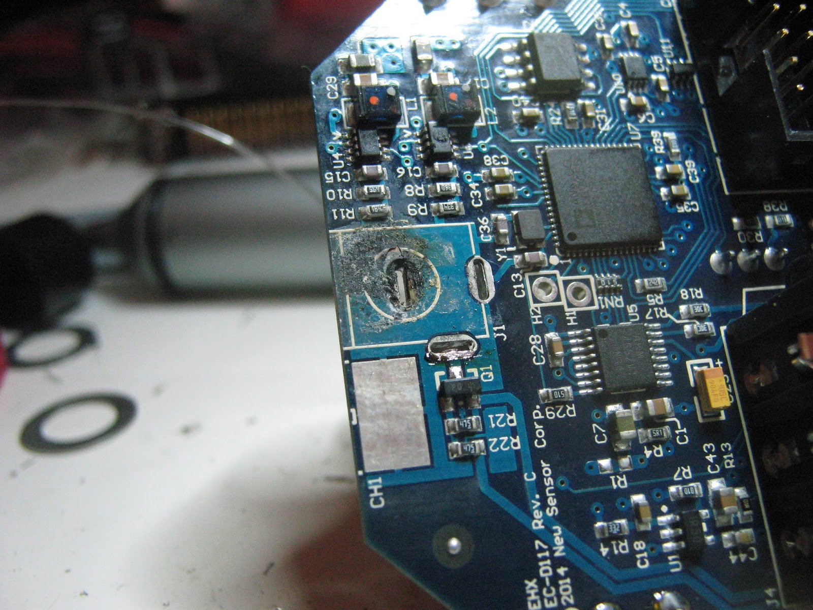
This is fairly heavily populated on the inside. This is the typical modern EHX style with pots, switches, footswitch, jacks and DC connector all mounted to a large PCB and then anchored to the case. A spring grounds the board to the enclosure. This style was designed to reduce assembly costs but it's hard to say if the quality is effected. It's a pain to get these boards out of the enclosure, I have been using a screwdriver to push in the DC jack but they get marred, so a plastic or wooden tool would work better. I like that the 3PDT footswitches is on it's own board with a ribbon cable, this switch will see the most force so strain-relieving it from the rest of the main board is a good idea.

It's a two PCB assembly, all surface mount ICs and passives. The main board appears to handle the input/output buffering, switching, modulation LFO and controls. The smaller daughterboard holds the BBD chips (4x BL3208A), the clock circuit and biasing and balancing trimmers.

Everything is analog, and apart from the BBDs EHX are only using common jellybean parts - SA571 companders, TL074, LM324 & 4558 opamps, LM13700 OTAs. These pedals should be repairable as long the SMD packages can be reworked (they can). The daughterboard is soldered to the main PCB with a 6 pin header strip, and there are some rubber pedal "feet" underneath to support it. I'm not a huge fan of this type of construction, anchoring the small PCB at one edge will allow it to lever and possible damage it. From what I've seen, the Memory Toy uses a similar construction method but the daughterboard is supported at two sides and is socketed instead of soldered. I desoldered the daughterboard to see if there were any backside components (none).
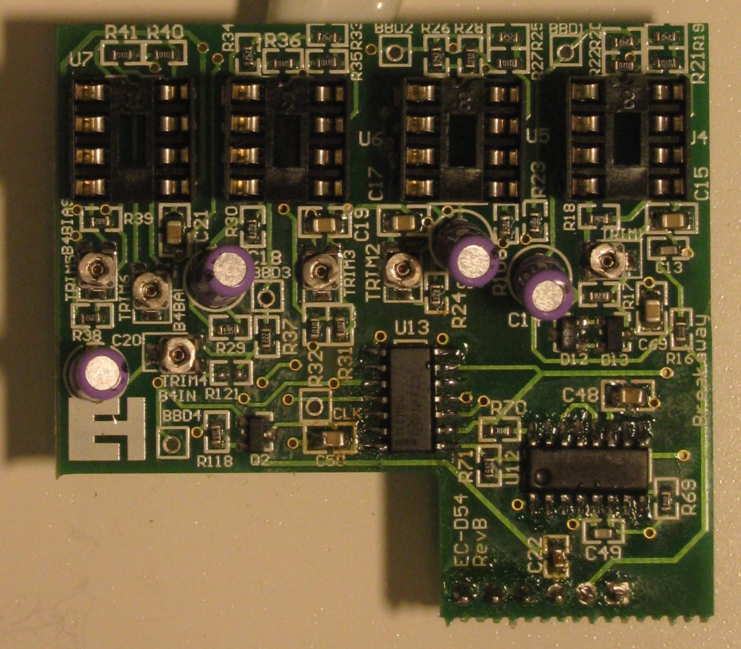
Main board - EC-D54 Rev. B

BBD Board -EC-D54 Rev. B. U13 was removed at this point.


After checking voltages at several ICs I started poking around with the oscilloscope. CMOS logic is used alongside analog ICs so 9V can be used everywhere, there are no voltage regulators onboard.
There is a helpful "CLK" test point on the smaller PCB that showed that I was getting no clock signal to the BBDs. There is a HEF4011 quad NAND-gate in use as an oscillator and an LM13700 configured as either a voltage-controlled resistor or capacitor to vary the frequency of oscillation, controlled by the modulation LFO.

I couldn't see any activity on the NAND chip (U13), so that was suspect. Lifting off the chip showed how it was connected on the PCB. I replaced the 4011 with a new one and the clock signal returned at the CLK test point. The clock frequency varies from about 5 kHz to 100 kHz. For 4 2048 stage BBDs this gives delay times from about ~40 ms to ~800ms, which seems correct. This means that bandwidth is limited to a few kHz at longer delay times,  which gives the characteristic dark sound. LFO is around 0.5 Hz in the slow ("chorus") setting.

After putting it back together it sounds great. I had some pretty bad clock noise at maximum delay time but this went away when I got it back inside the enclosure. Longer repeats are dark, and I don't hear much distortion (though I'm not sure if I would recognize if it was there). Modulation is nice, I find the triangle wave much more useful than the square. It doesn't do the clean repeats with strong attack that digital delays allow, but that's probably not what it's meant to do either.

I don't know why the 4011 failed. I did notice that the specific part used is only rated for ~1mA output current, it's possible that driving the input capacitance of the BBDs at high clock frequencies exceeded this (?) To be safe I used a MC14011 that can supply 8.8mA.

As for scope for mods, a dedicated modulation speed control would be nice. This can be done through the expression pedal jack but as it's only a single resistor in the LFO circuit controlling the rate I may attempt it there. It doesn't really oscillate when feedback is at maximum, so a series resistor with the feedback pot might have be jumpered to get it to break into oscillation.