Showing posts with label Electro-Harmonix. Show all posts

Thursday, 28 March 2019

Electro-Harmonix Micro Pog

I think this is the last entry in the EHX POG series that I haven't repaired. As usual, this came from eBay and doesn't work. No signs of life.


On first inspection, it looks like the diode in the switching power supply is trying to escape the PCB. I don't think that overheating could cause this without scorching the board, someone probably attempted to desolder this. My multimeter confirmed that this diode was a short circuit, so that's probably the fault. The diode is an SS14, which is also the same part used for input polarity protection. The switching IC is a CS51413 buck regulator.


I removed the diode and still measured a short across it's pads, so the switching chip is probably bad. That came off as well.


I ordered a replacement CS51413 but actually received a CS51414, which was annoying. However, the CS51313 and CS51414 are very similar, the '313 has an external sync pin where the '514 has an external bias pin. The Micro POG doesn't actually route pins 4 & 5 anywhere, so either chip can be used. I suspect that both are the actually the same die, with different pads broken out to external pins.

After replacing the controller IC and the switching diode, I still had a short from output voltage to ground. The output capacitor (C3) is also connected across these nodes, so I removed it and then the pedal worked. C3 is filtering the output of the 3.3V switching supply and doesn't seem to be always necessary. I don't know the value of C3, but the datasheet recommends 100uF. A 100uF ceramic capacitor in this package is actually quite expensive, so I used a 47uF.


The rest of the pedal is very similar to other Electro-Harmonix XO series units. There's a PIC18F2431 microcontroller, a DSP56364AF100 DSP and a PCM3052A audio codec.


When I had this working the "Octave Up" pot felt a bit weird. The shaft had actually broken away form the pot and had been re-inserted. I replaced it with a new 5Kohm part from Smallbear which is an almost perfect match.

 
That's it. Maybe someday I'll look at the HOG series as well.

Friday, 8 February 2019

2 70s Electro-Harmonic Small Stone phasers

2 vintage Electro-Harmonix Small stone phasers. The artwork for both of these is almost identical to the 90s reissue (which uses LM13700 OTAs) but the lack of any LED indicators gives away that these are older - probably late 70s or 80s.


Small Stone #1

I think this is the pedal I have owned the longest with repairing. I started buying broken stuff  to repair from eBay in 2011, and picked up a couple of vintage Big Muffs. One was a lot that came with this pedal, a Small Stone, pretty much as pictured - no knob, no pot, no switch and a lot of broken wiring.


The Small Stone has 4 phase shifting stages, using 1 OTA as an LFO and 4 more as variable RC filters that give varying phase shifts. Early versions of the Small Stone used CA3094 OTAs branded as "EH1048", a house-marking for Electro-Harmonix. This version is an "Issue J" and has the 5 EH1048 chips, dated to 1977.

Issue J

EH1048 - 1977, week 32.


I bought a new 24mm reverse log pot, installed a 3PDT switch and re-wired the pedal (true bypass, why not). It didn't pass an effected signal. I think I put it aside at this point, I suspected that the OTAs might be bad and didn't have any replacements.


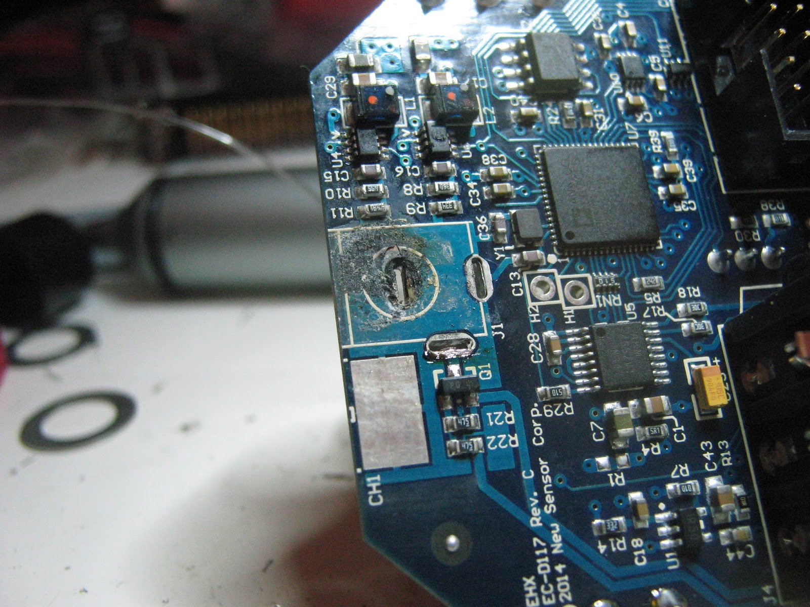
I came back to this recently. The oscilloscope showed that there was no LFO signal anywhere on the board, even though most of the voltages on oscillator OTA looked reasonable. I bought an RCA metal can CA3094 and replaced it - now I had an LFO, but still no wet signal. Looking at the input and output pins of each OTA, I could see that the first stage was phase shifting, but the second had no output. I shorted together the input and outputs of the second stage, and now I had a phase-shifted signal. It wasn't quite as deep as it should be, with only 3 or 4 stages active, but it verified that the other two ICs were good. I ordered one more CA3094 to replace the dead EH1048, and complete things.

Before re-housing
I sourced a new hockey put knob that fit the new 24mm pot. Originals are hard to come by, but it fits the right aesthetic.


This was inspected by... Elsa? Cheers, Elsa.

There is usually some foam behind the PCB on the back panel of the housing. The PCBs just hang off the back of the rate pot, the foam is to prevent it from shorting out on the back panel. This foam had perished, so I taped some card down to insulate the PCB instead.

Small Stone #2

This second unit is a similar vintage, I picked it up hoping it might help repair the first one.


This is a slightly different PCB (with a phenolic substrate instead of fibreglass?), but looks to be the same circuit more-or-less. It also has 5 EH1048s, dated to 1979.

This one actually worked despite being sold as faulty (this is not that unusual). It just had a couple of quirks. It was a big help in verifying the switch wiring on the other unit, and for taking reference voltage readings off the OTA chips.

Phenolic PCB, instead of fibreglass?
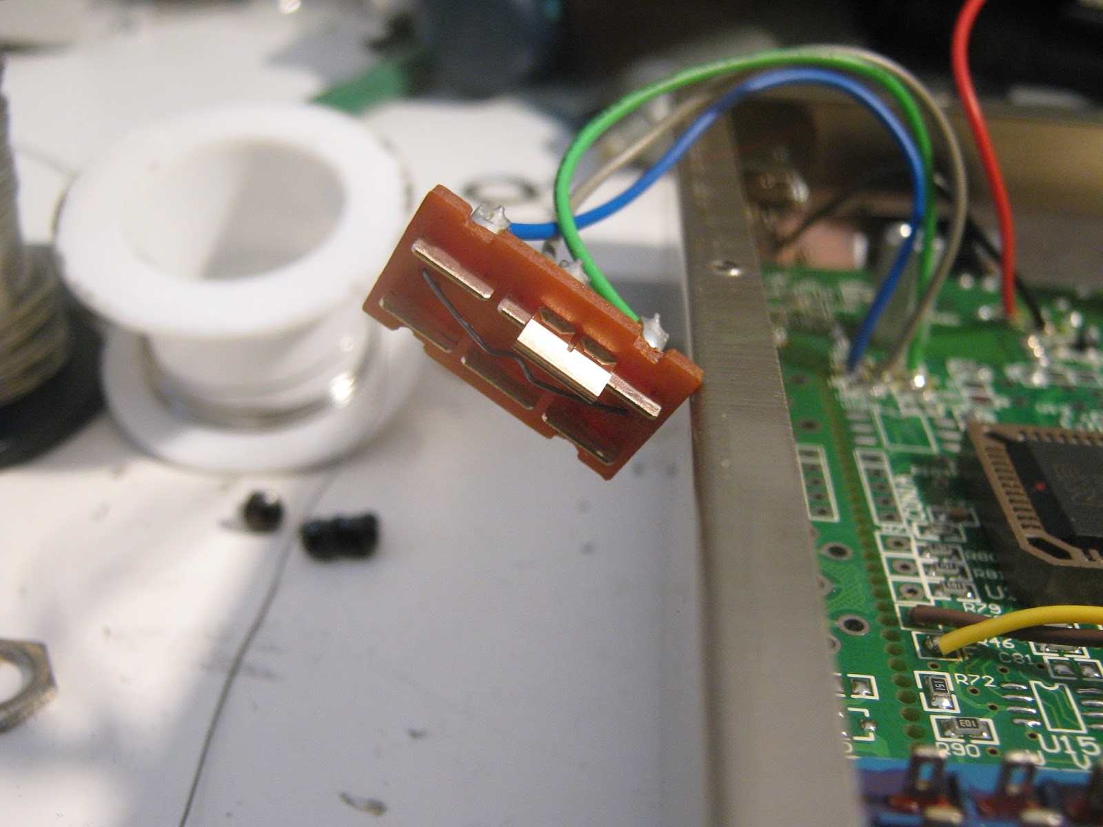
The first was that the rate pot had some odd damage, the casing was partially open. I guess this could have been caused by dropping the pedal onto the knob, or by pulling on the PCB while it was still attached to the enclosure. Or during factory assembly, this was EHX after all. This was easy to close and re-crimp with pliers.

Opened pot housing...

...closed again

The second was that it would start to oscillate with the "color" switch in the up position and no input. It works fine with a guitar connected, or a buffered pedal in front of it, but with no cable or dangling unconnected cable it will start to ring at the top of the phaser sweep. As far as I can tell this is just something that this revision does, to fix it I would have to switch to a shorting input jack or modify the pedal to reduce the positive feedback when the color switch is in the up position, neither of which I really want to do.


These turned out really well. Feels good to have them done. They sound almost identical, the only change that jumps out is that the two different brands of pots don't quite match up - the plastic shaft CTS pot physically rotates further than the new Alpha pot, so the rates are slightly different when the pointers are matched by eye.
I don't have a modern Small Stone, or a Sovtek, to compare with. They definitely sound smoother than JFET phasers I'm used to.

One or both of these will probably hit Reverb in the next couple of days, get in touch if interested.

Electro-Harmonix Stereo Memory Man (EH-7811)

The classic, basic, no-frills BBD delay. This is an EH-7811 revision, dating from around 1980 based on IC codes. This version is main powered (240V), runs at +/-15V internally, Panasonic MN3005. There is no LED, I think this was the last version without one. There is an Echo/Chorus switch which probably reduces delay times, and in-phase and out-of-phase outputs for a "stereo" effect.

This is another one that I have had a for a while, and later came back to. I bought this a couple of years ago and nearly got it working, then hit a dead-end.

It was pretty dirty on first inspection, and missing a knob for the blend control. The power cable had been shortened to a ridiculous length, about six inches, making it awkward to work on.

Before cleaning...

The original eBay picture shows this off:


The insides show that the PCB is complete with no obvious damage. It does anchor everything off of board-mounted pots which are only on one side of the large PCB - the other end floats and tends to cantilever.

PCB as received

The delay/chorus switch is almost entirely missing, just the frame left.

Interior of case, Echo/Chorus switch.

Closer inspection of the PCB found that the Blend potentiometer's pads had all craclked off. The pot was still hanging onto the board, but nothing was electrically connected. I ran some small jumpers from the pot back to the nearby traces. I also installed a new sliding switch. I referenced a schematic for the later EH-7811B at David Morrin's excellent site. The main difference (apart from the LED) seems to be that this version has an extra 741 opamp to invert the delay signal for the out-of-phase output.

At this point, I had some signal coming thorough, but hugely distorted. All output opamps were saturated, sitting at ~ 13 or -13 volts. I socketed and replaced some of the opamps with no change. There was a DC offset being introduced somewhere.

I had a few ideas:
  1. dead opamp, or opamp feedback network. No changes when swapping opamps and measuring feedback resistors.
  2. leaking AC-coupling capacitors. I replaced some 1uF caps of a type I had seen fail before with modern film caps, no changes
  3. Missing ground node somewhere...
This went back into the "fix later" box for a while. I dug it out and went over some of schematics for other revisions and noticed that one side of the blend knob should be connected to ground. My blend knob had been cracked off the board, I could barely see a small track below the pot's pads that should have been connecting to ground.

I ran another jumper wire to ground, and now all the outputs were sitting at 0V.


I fitted a new mains cable so that is actually usable. There is no internal fuse, so I changed the cable fuse to a 3A part. I tried the original opamps in the sockets, but the outputs got noticeably more noisy. Maybe semiconductor processing has improved to the point where new 4558s and 741s are less hiss-y.

There was some serious clock whine, especially at long delay times. Fortunately I was able to completely trim this out.

PCB after repairs.

PCB after repairs, parts replacement.

I've said before I haven't noticed huge differences between analog delays based on BBD types. I had the Aqua Puss at hand for comparison between a V3205 and MN3005. The Memory Man sounds cleaner, if that makes sense? Less distortion on each repeat, a bit closer to the original signal. Still sounds like analog delay, just not as overblown.

Reassembled.

Thursday, 31 January 2019

Another Electro-Harmonix Freeze

I got another Electro-Harmonix Freeze fairly cheap, it sounded like it had been killed by an incorrect wrong power supply. I took it apart and found that it was a newer revision than I had seen before, the board was EC-D68 Rev C (the last one was Rev B). The main difference I notice was an AK4558 codec instead of PCM3052A.

Freeze Rev C PCB, flash ROM temporarily removed.
Main PCB, LM317 temporarily removed.

There was no sign of life, I found that the series Schottky diode at the 9V input had failed open-circuit and that the LM317 had an internal short between it's input and output pins. The fast/slow/latch mode switch also fell to pieces when the board came out of the enclosure.

I replaced the bad diode with an SS14L (it was the correct size and I already had some at hand) and installed a new LM317. I thought that the LM317 was supplying 3.3V to the DSP and this would fix everything. Instead, the pedal would pass a clean signal but with a clicking sound once or twice per second. I found out that LM317 is actually used as a 1.25V regulator, which is only used for the analog VCC of the DSP56374.

I thought the clicking may be the DSP watchdog timer firing, possibly because it was missing program code, so I removed the flash memory and dumped it. It was a perfect match for the dump I made of the first pedal I repaired, so no problem there.

Measuring power at every IC I found that the 5V rail was high at around 5.9V and the 3.3V supply was sitting at 3.9V. I thought that U5 and U8 (both SOT-89 packages) were also voltage regulators and that maybe they had been damaged as well. I also noticed that U6 is connected to the reset pin of the DSP, and it was resetting the DSP every second or so. My guess is that U6 (also connected to the 3.3V supply) is some kind of voltage supervisor and it is resetting the DSP because of an incorrect 3.9V at VCC.

I found a great picture at freestompboxes (thanks to Steven_M!) showing that on previous version, U5 was 78L05 (5V regulator) and U8 was BA932 (who knows, but from context it has to be a 3.3V regulator).

U5 & U8 on another revision.

The Rev C board in front of me had "BA420" on both chips. Possibly EHX decided to run all 5V parts off of 3.3V, and doubled up on regulators? I don't know.an

To test this out, I decided to remove both chips and apply 5V and 3.3V from  external power supplies.

U5 & U8 removed, external power applied

This set up was a little awkward, but everything work correctly. Current draw looked totally reasonable, 19mA from the 5V supply and 21mA from the 3.3V. No resetting, no clicking, and the pedal could freeze audio in all 3 modes.

Current draw on 5V and 3.3V supplies.

I ordered L78L05ABUTR and MCP1804T-3302I/MB as replacement 5V and 3.3V SOT-89 regulators. I also used 2MD3T2B2M2RE as a replacement switch. This replacement is not threaded for a nut, but recent version of the Freeze don't look like they are threaded either. Pedal works like new.


Sunday, 18 February 2018

Electro-Harmonix Pitchfork

I don't know if the PitchFork exists alongside the POG series for market segmentation reasons or as a direct competitor to the Whammy pedal. Whatever the reason, EHX have another polyphonic pitch-shifter/harmonizer with a slightly different feature set, and strangely, a lower price. This one will add a harmonized voice at a selectable interval, at a higher or lower pitch or both. You also get a clean blend. There is an expression pedal control and the footswitch can be set to work in a momentary mode, which suggests Whammy style punch-ins, but it does POG style octaves as well.


The insides are very similar to the newer POG pedals, with an Analog Device Blackfin DSP (ADSP-BF592) and a AKM AK4552 24-bit/92 kHz ADC/DAC. There is also a 25L1005 serial flash with the program code - I did end up desoldering and dumping this in case I come across another and need it.

Picture taken after repair - clean.


Taken before repair - PCB appears cloudy

This one would not show any signs of life, and turned out to be shorting out my power supply. The reverse polarity diode (D2) on the back of the DC jack measured as a short circuit, so I removed it and the pedal worked! For about 10 or 15 minutes. Something else between 9V and ground was shorting.

11-detent "Mode" pot showing some stains
After a little while spent probing around and occasionally getting a short burst of life followed by nothing, I noticed that one pot had some corrosion on the back sides. I desoldered it and wire-brushed it until it was clean but couldn't figure out how this would be the cause of the problem. The corrosion was probably from some liquid spilled into the pedal.

I could see some kind of dirt at the power jack, so I removed it and things were then pretty obvious, some liquid had been trapped between the jack and PCB and had corroded the board, causing intermittent shorts.

Original DC jack

..and underneath the jack
Some scrubbing with PCB cleaner and a new DC jack later and it is rock-solid. The rest of the board was cleaned as well, what looked like cloudy flux residue was probably stains from dried liquid.

This is a pretty clear case, something was spilled and the pedal was never taken apart and cleaned afterwards. If it had been looked after at the time then no parts would have needed replacement. Underneath DC jacks and instrument jacks are probably the worse places for this, as they can trap liquid easily.

Monday, 14 August 2017

Electro-Harmonix Pog (Big Box)

binary is hereFollowing the Nano POG & POG2, here is the original big box Electro-Harmonix POG. The big POG has mostly the same set of features as the POG2 - it doesn't have presets and the filter has fewer settings, but there are separate detune sliders for the 1 & 2 octave up harmonies.

No slide pots were placed this time
In keeping with a trend I've noticed with EHX products, it's completely different on the inside than the other POG pedals. The POG2 and Nano POG use Analog Devices BlackFin DSPs, the OG POG is much more late 90s and has a DSP56364 and a 8051-style P87C52 MCU, just like some Line 6 products, or the Digitech Whammy. I have no idea why this cheap microcontroller family is so commonly found alongside the DSP56K series but I'm starting to suspect there is an application note somewhere that shows how to use these parts together. The AK4552 codec and 2272 & 5532 opamps are also very familiar by now. A TLV1543 ADC reads out the slider positions.


DSP56364

This pedal is also an outlier in that the complete factory schematic is online at Freestompboxes. The P87* series MCUs are OTP (but could be replaced with a compatible programmable part), so I have dumped this one. There is no other programmable part on the board so this should hold firmware for both the MCU and the DSP. The binary is here.
There are a lot of unpopulated parts in the PCB layout, some may be used for development and some look abandoned. There are footprints with silkscreen labels that indicate that they are for MIDI control and the schematic also indicates MIDI was planned at some point. I didn't experiment.

Trashed slide switch

No complicated fix for this one, once I had rigged up an 18V supply I found that the LPF mode switch was broken and a couple of wires looked like they were about to come off the board. After some solder touch ups everything worked fine. It sounds very much like the POG2, but as I don't own one anymore I couldn't do a direct comparison.

Tuesday, 6 June 2017

Electro-Harmonix Freeze

The Freeze launched in 2010(?) and has been very popular. It's essentially a very short looper with some windowing to hide the "jumps", giving a smooth drone of whatever was captured. There is a decent claim for this being a genuinely new effect, even though there have been reverbs, delays and granular synth effects that can get similar results there is nothing that competes with it directly. I have never played with one so I've been looking out for cheap broken units.


This one passes no signal, crackles a little bit and I probably overpaid for it. The insides are more simple than I expected, a 56k-series DSP (DSP56374), a PCM3052A ADC/DAC, a serial EEPROM for the DSP code, an LM317, a TLC2272 opamp and a tiny SOT23-5 package that I am fairly sure is a NC7SZ66M5X SPST switch. It's surprising to see the DSP56374 as these are fairly long obsolete now, and other EHX products are using Analog Devices DSPs that are still in production. This might have been a 2010 purchasing decision, or they may have large stock as the 56k series is also used in other older EHX products. The PCM3052A is also fairly old but I have seen pictures of other Freeze revisions that used different codecs.


This Freeze passed no signal in bypass or effected mode, just some crackling noises. The LEDs did light up according to the Slow/Fast/Latch switch, and as there is no microcontroller I have to assume that the DSP handles this and that it is probably working correctly.

I fed in a test signal and traced it with an oscilloscope. I could see it at the input jack, through the ferrite bead and then at one of the input pins on the opamp (U2). It appeared to be wired as a buffer (makes sense) and there was nothing on the output pin. So the digital end was probably fine, it was just not being fed an input signal. Replacing this opamp fixed it.

In process of replacing U2

 To be honest, sometimes the process of fixing stuff is more fun than playing with it afterwards. The appeal for me is a mixture of curiosity about the technical stuff and the musical/creative aspect, and it can be easy to switch the things off after testing if it's "just" another delay, overdrive or whatever. The Freeze has consistently been a lot of fun every time I plugged into it. On the day I got it I spent a lot more time playing with it than I did repairing it (that has to count for something). I have used loopers before and found that they need a bit of planning and practice to use well, the Freeze is very immediate and it lends itself to noodly bullshit in the first couple of minutes of use, especially in latching mode. Thumbs up.

I expected to see some kind of microcontroller as the DSP 56k series have usually been paired with one in the previous pedals I've looked at, usually some kind of 8051 core (Line 6, Digitech examples). As the Freeze is a single processor design it might make this an interesting one to reverse engineer, there should only be code for a single architecture in the EPROM. I would guess that the effect is fairly simple, but the magic is in the delay length and the filtering to avoid clicking or popping. There is an assembly language manual available from NXP, I've looked for a disassembler and have found that it is supported by Ida Pro (great, but the full version is out of my price range) and some pretty old 90s tools that I haven't tried yet. If there is a decent free tool please let me know.

First step is dumping the EPROM and figuring out if the code is on there or if the DSP is pre-programmed. OpenOCD does support the DSP56374, so the programming header may be another option.

Sunday, 29 January 2017

Electro-Harmonix Deluxe Memory Boy

Another quick one. This is the high-end version of the Memory Boy that I've looked at before. The Deluxe adds an extra gain control, tap tempo, tap divide, a rate control for modulation, an effects loop and the ability to control rate, depth, feedback or delay time with an expression pedal.
I got this used with a fault, the seller said the delay signal was very quiet compared to the dry. I plugged it in, and sure enough the delay was kind of weak. The manual for this one says that the added Gain control goes from -6 dB to +20 dB. When I put it straight up at 12 o'clock the delay seems to match the dry signal in terms of volume. I can't find anything wrong with it so I'm just taking a look inside.


Both PCBs.

The guts are similar to the Memory Boy, 4558/LM324/TL072 opamps, SA571 opamps and of course the 4 BL3208A BBDs. There is an ATMega16 microcontroller doing the tap-tempo and probably modulation waveforms as well. There is a JTAG port but I don't know how to dump the ATMega through JTAG, and I'm fairly certain it will be read-protected anyway.

BBD board, front
BBD board, backside

The BBDs are on a daughterboard, as per the Boy. This time they are connected with header pins and sockets and held down with screws into brass inserts instead of soldered to the main board. On the backside is the same 4011 IC used as an oscillator for the BBD clocks.


Main board uncovered

Underneath the BBD board we can see an LM13700, most likely modulating the clock frequency in the same way that the Memory Boy worked. I was a little surprised as I thought the ATMega would generate all the clock signals, it must just generate control voltages to the LM13700 to adjust the clock rate.

One nice feature is that the full IC part numbers are on the silkscreen, which should make life easier for anyone attempting to repair one.

The tap-tempo features are nice, but the rest of the pedal is essentially the same core delay as the Memory Boy. The tap-tempo does seem to allow longer delay times than the knob, around 1 second (by ear).

I'm not the biggest fan of this series, I prefer the Ibanez ES-2 for analog delays. This version is definitely an upgrade over the original if you can afford the real estate.